Sheet metal manufacturing guide from material selection to finished parts
What sheet metal manufacturing includes
Sheet metal manufacturing is the controlled conversion of flat metal sheet or coil into brackets, panels, enclosures, covers, frames, housings, ducts, shields, and many other industrial parts. It is not one process. A typical route may combine laser cutting or punching, press brake bending, stamping, welding, hardware insertion, surface finishing, and inspection. The right route depends on part geometry, material, thickness, annual volume, tolerance requirements, surface appearance, and whether the design is still changing.
For engineers and buyers, the key is to balance shape, manufacturability, and repeatability. A part that looks simple in CAD can become expensive if it needs many bend setups, tight cosmetic controls, poor material yield, or secondary rework. A manufacturable design uses the strengths of sheet processes: fast cutting, efficient nesting, predictable bends, and repeatable assembly.
More topics in industrial production methods are covered in the manufacturing processes category.
The typical process flow from CAD to finished part
Engineering inputs and manufacturability review
Most sheet metal projects start with a 3D model, 2D drawing, material specification, thickness, finish requirement, tolerance notes, and target quantity. The manufacturability review checks whether the part can be unfolded into a flat pattern, whether bends have enough clearance, whether holes are too close to bend lines, and whether the specified material can meet the forming and finishing requirements.
This stage also identifies which dimensions are function-critical. Not every dimension needs a tight tolerance. Over-tolerancing adds inspection time and may force slower processing without improving performance. A practical drawing separates critical interfaces from general dimensions, cosmetic zones, and non-critical edges.
Cutting, blanking, and nesting
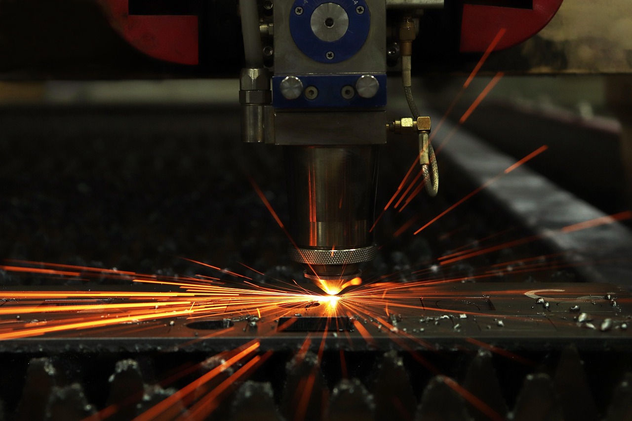
The flat shape is produced from sheet or coil by cutting or blanking. Common methods include fiber laser cutting, punching, turret punching, waterjet cutting, plasma cutting, shearing, and die blanking. Laser cutting is widely used for flexible production because it can cut complex profiles without dedicated hard tooling. Punching is efficient for repeated holes and standard features. Stamping or die blanking becomes more attractive when volume is high enough to justify tool cost.
Nesting is a major cost factor. Parts are arranged on a sheet to reduce scrap while maintaining grain direction, surface requirements, and safe handling. Small changes to part orientation, tab placement, or edge conditions can improve material utilization.
Forming and bending
After cutting, many sheet metal parts are formed by press brake bending, roll forming, stamping, deep drawing, hemming, flanging, or embossing. Press brake bending is common for prototypes and low-to-medium volumes because it uses general tooling. Progressive die stamping, transfer stamping, and roll forming are better suited to repeat production where tooling investment can be spread across many parts.
Bending introduces springback, inside radius variation, and bend allowance considerations. Material grade, thickness, tooling opening, bend angle, and grain direction all influence the final shape. Designers should not assume that a sharp internal corner can be formed in every material. Minimum bend radius should be checked against the material and process before release.
Joining and assembly
Sheet metal assemblies may be joined by spot welding, MIG welding, TIG welding, laser welding, clinching, riveting, screws, tabs, adhesives, or inserted hardware. The joining method affects strength, appearance, heat distortion, corrosion behavior, and serviceability. Welded assemblies may need fixtures to control distortion. Riveted and screwed assemblies are easier to repair, but they can add fastener cost and assembly time.
Finishing and inspection
Finishing can include deburring, grinding, brushing, passivation, anodizing, powder coating, plating, painting, polishing, or protective film. Inspection may include dimensional checks, angle verification, thread inspection, weld checks, coating thickness checks, and visual inspection. For thermal cutting quality, ISO 9013:2017 is often referenced because it classifies cut quality and geometrical tolerances for oxyfuel, plasma, and laser-cut materials. For machine safety in the United States, OSHA rules and guidance for mechanical power presses are commonly used in safety programs involving shearing, punching, forming, and related operations.
Main sheet metal manufacturing processes and where they fit
| Process | Common use | Strengths | Limitations |
|---|---|---|---|
| Laser cutting | Flat profiles, prototypes, complex outlines | Flexible, no dedicated cutting die, good for design changes | Edge quality depends on material, thickness, settings, and assist gas |
| Punching and blanking | Holes, slots, forms, repeated sheet features | Fast for repeated features and standard shapes | Tooling limits feature geometry and may leave burrs |
| Press brake bending | Brackets, boxes, flanges, channels | Flexible forming with standard tooling | Requires bend access, proper radii, and setup control |
| Stamping | High-volume formed parts | High repeatability and speed after tooling is built | Tooling cost and lead time are significant |
| Deep drawing | Cups, shells, pans, drawn housings | Creates seamless hollow shapes | Requires suitable material ductility and careful die design |
| Roll forming | Long constant-section profiles | Efficient for continuous production | Less suitable for short runs or frequently changing profiles |
| Welding and fastening | Assemblies, frames, enclosures | Combines multiple parts into functional structures | Can add distortion, inspection needs, and labor cost |
| Surface finishing | Corrosion protection, appearance, wear resistance | Improves function and market-ready appearance | Requires finish allowances, masking plans, and handling control |
The process choice should follow the production problem, not the other way around. A prototype enclosure may be best made by laser cutting and press brake bending. A small bracket used in hundreds of thousands of units may justify a progressive die. A long cabinet rail may be more economical through roll forming than through repeated press brake operations.
Material and thickness decisions that shape the process
Material selection affects strength, corrosion resistance, weight, appearance, weldability, formability, cost, and lead time. Mild steel is widely used where strength and cost matter and where a coating can provide corrosion protection. Stainless steel is chosen for corrosion resistance, hygiene, appearance, or heat resistance, but it may require more attention to tooling marks and springback. Aluminum offers low weight and good corrosion resistance, although its forming behavior and welding requirements differ from carbon steel. Galvanized sheet provides a zinc-coated surface but requires care during welding and finishing.
Thickness is equally important. Thin sheet can be cut and formed quickly but may distort during welding or finishing. Thick sheet increases stiffness and load capacity, but it may require larger bend radii, higher press force, slower cutting, and different handling. In many industries, material thickness may be specified in millimeters or by gauge. Because gauge systems vary by material type, drawings should avoid ambiguity by listing the actual thickness and tolerance where it matters.
Grain direction should not be ignored. For many materials, bending across the grain is generally more favorable than bending parallel to the grain because it reduces the risk of cracking on the outside of the bend. For visible parts, sheet surface direction can also influence brushed or grained finishes. If appearance matters, the drawing should identify cosmetic faces and finish direction.
Design rules that reduce rework and cost
Good sheet metal design does not mean making every feature easy at the expense of function. It means placing functional features in a way the process can repeat. The following rules are useful starting points, but final values should be confirmed with the selected manufacturer, tooling, and material grade. See also: buying guides.
- Use realistic bend radii. Very small inside radii increase cracking risk and may require special tooling. A practical radius improves formability and repeatability.
- Keep holes away from bend lines. Holes, slots, and threads placed too close to a bend may stretch or distort during forming.
- Add bend relief where needed. Relief cuts can prevent tearing, bulging, or interference near bend ends.
- Avoid unnecessary tight tolerances. Tight tolerances should be reserved for mating interfaces, datum features, sealing surfaces, and safety-critical geometry.
- Define datums clearly. Inspection becomes more reliable when the drawing shows which surfaces or holes control alignment.
- Plan for burr direction. Burrs can affect assembly, safety, coating, and electrical contact. Critical edges should be called out.
- Account for coating thickness. Powder coating, plating, and paint can change fit, hole size, thread engagement, and grounding surfaces.
- Limit setup complexity. Multiple bend directions, closed shapes, and features that block tooling access can add cost or make forming impossible.
Legacy drawings may reference general tolerance standards such as ISO 2768, while newer projects may use different company or industry specifications. The safest approach is to state the applicable standard, revision, critical dimensions, and inspection method rather than relying on an unclear title block note.
Cost drivers in sheet metal manufacturing
Cost is shaped by more than material weight. Setup time, tooling, machine time, labor, finishing, inspection, packaging, and scrap all matter. For low-volume work, programming, setup, and handling can dominate the unit price. For high-volume work, material yield, cycle time, tool life, and automation become more important.
Cutting cost is influenced by material type, thickness, pierce count, contour length, edge quality requirements, and nesting efficiency. Bending cost depends on the number of bends, tool changes, part size, handling difficulty, and whether operators need special gauges or fixtures. Welding cost is affected by joint length, access, distortion control, cosmetic grinding, and inspection level. Finishing cost depends on surface area, masking, color changes, coating specification, and the number of visible surfaces.
Design changes are usually cheaper before tooling is built and before finishes are specified. Once a stamping die, welding fixture, powder coating mask, or inspection gauge is made, a small design change can have a large cost impact. For this reason, early prototypes should focus not only on shape but also on the likely production route.
Quality, safety, and supplier questions
Quality control in sheet metal manufacturing should match the function of the part. A decorative enclosure needs strong cosmetic standards, while an internal mounting bracket may need positional accuracy more than surface perfection. Common quality checkpoints include material verification, first-article inspection, bend angle checks, hole location measurement, weld inspection, coating checks, thread verification, and packaging review.
Safety is also part of manufacturing quality. Cutting machines, press brakes, mechanical power presses, welding stations, and finishing lines all involve hazards that must be managed through guarding, procedures, training, and maintenance. OSHA describes mechanical power presses as machines that shear, punch, form, or assemble metal or other materials by means of tools or dies attached to slides or rams. That definition is useful because it highlights why point-of-operation guarding and controlled work practices are central to sheet metal production.
When comparing suppliers, ask practical questions instead of only requesting a unit price:
- Which cutting and forming processes will be used for this part?
- What material grade, thickness tolerance, and surface condition will be supplied?
- Which dimensions will be inspected during first-article approval?
- How are bend deductions, flat patterns, and revisions controlled?
- What finish specification, masking requirement, and packaging method are assumed?
- Does the quoted route change at higher volumes?
- Which features are driving cost, lead time, or manufacturability risk?
These questions help turn a drawing into a controlled production plan. They also show whether a part should remain a flexible fabricated component or move toward dedicated tooling as volume grows.
Frequently asked questions
Is sheet metal manufacturing the same as metal fabrication?
They overlap, but they are not identical terms. Sheet metal manufacturing focuses on parts made from flat sheet or coil, usually through cutting, forming, joining, and finishing. Metal fabrication is broader and may include plate, structural sections, tube, bar, machining, welding, and large assemblies.
Which process is most suitable for low-volume sheet metal parts?
Low-volume parts are often made with laser cutting or punching followed by press brake bending because this route avoids dedicated stamping dies. However, the most suitable route depends on thickness, geometry, tolerance, finish, and material availability.
When does stamping become a better option?
Stamping becomes more attractive when production volume is high, the design is stable, repeatability is important, and the tooling cost can be justified. It is less attractive when the design is changing frequently or when annual quantities are too low to recover tool investment.
How should tolerances be specified on a sheet metal drawing?
Critical interfaces should receive specific tolerances and datum references. Non-critical edges can often use general tolerances. The drawing should state material thickness, finish requirements, coating effects, and any inspection standard that applies. Avoid applying tight tolerances to every feature unless function requires it.
What files should be prepared before requesting a quote?
A useful package includes a 3D model, a 2D drawing, material grade, thickness, finish requirement, quantity range, cosmetic requirements, hardware details, revision level, and any special inspection or packaging needs. Clear inputs reduce assumptions and make quotes easier to compare.