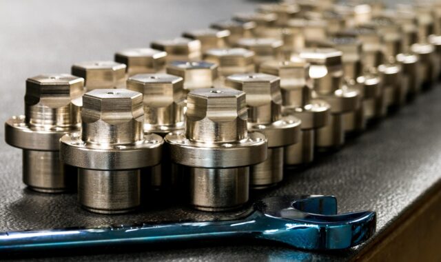
Booster precision components for turbo, brake, and hydraulic systems

What booster precision components do in mechanical systems
Booster precision components are machined, ground, formed, or finished parts that help a booster system increase pressure, airflow, vacuum assistance, or actuation force while maintaining sealing, alignment, and response. In mechanical manufacturing, the term can refer to turbocharger parts, brake booster parts, hydraulic pressure intensifier parts, pneumatic booster parts, and related pump or actuator assemblies. The shared requirement is not just tight tolerance. These parts need controlled fit, repeatable geometry, suitable surface texture, and traceable inspection because they often operate under high speed, cyclic loading, pressure fluctuation, or safety-related duty.
For readers comparing precision components across different assemblies, booster parts are useful examples of how small dimensional errors can create large system effects. A shaft journal that is slightly out of round, a sealing bore with the wrong surface finish, or a valve seat with poor concentricity may not look severe on a drawing. In service, however, those details can affect leakage, friction, vibration, boost response, or service life.

Why the word booster covers several engineering meanings
The keyword “booster precision components” can cause confusion because “booster” is used in different ways across industries. In an engine air system, a turbocharger or supercharger boosts intake air pressure. In a braking system, a vacuum, hydraulic, or electric booster assists pedal force. In industrial hydraulics, a pressure intensifier or booster raises pressure for clamping, testing, forming, or waterjet cutting. In pneumatic equipment, an air booster raises line pressure for a specific process zone.
These systems differ in medium, temperature, speed, and regulation method. They still share one design challenge: the booster must convert available energy into higher output without uncontrolled leakage, instability, or wear. That is why precision parts are central to the function, not simply supporting hardware.
| Booster application | Typical precision components | Critical manufacturing concern |
|---|---|---|
| Turbocharger or air boosting | Shafts, compressor wheels, turbine wheel assemblies, bearing housings, thrust parts, seal surfaces | Balance, concentricity, heat-resistant materials, surface integrity |
| Brake power assist | Booster housings, valve bodies, pushrods, diaphragms, check valve interfaces, master cylinder interfaces | Functional alignment, sealing, corrosion control, safety validation |
| Hydraulic intensifier or pressure booster | Pistons, plungers, check valve bodies, seats, sleeves, seal carriers, cylinders | Seal support, bore quality, hardness, fatigue resistance, pressure containment |
| Pneumatic booster | Spools, cylinders, rods, poppets, seats, ports, guide sleeves | Low-friction motion, air leakage control, repeatable valve timing |
The precision features that matter most
Most booster components contain several features that must work together. A drawing may list individual dimensions, but the assembly depends on relationships: coaxiality between a bore and a shaft, perpendicularity of a seating face, runout of a rotating feature, or parallelism between pressure-loaded surfaces. ASME Y14.5-2018 is widely used for geometric dimensioning and tolerancing because it provides a common language for symbols, rules, definitions, requirements, and interpretation of GD&T on drawings and digital product definitions. ISO 286-1:2010 is commonly referenced for the ISO code system of tolerances on linear sizes, particularly cylinders and two parallel opposite surfaces.
Fits and clearances
Booster assemblies often combine sliding fits, rotating fits, interference fits, and sealed static joints. A hydraulic plunger may need enough clearance to move smoothly while allowing the seal system to carry pressure. A turbocharger bearing housing must control the relationship between oil film, shaft motion, and thermal expansion. A brake booster pushrod interface must transfer motion predictably without binding or excessive free play.
A tight tolerance is not automatically the right tolerance. The correct tolerance is the one that supports the functional stack-up, manufacturing capability, material behavior, and inspection method. Over-tightening noncritical dimensions can raise cost without improving performance, while an unclear datum relationship can make a part difficult to assemble consistently.
Surface texture and sealing behavior
Surface texture can be as important as size. ISO 21920-1:2021 addresses the indication of surface texture by profile methods in technical product documentation. In booster components, the surface requirement depends on the contact condition. A seal-running surface usually needs controlled roughness, lay, and freedom from defects that could damage the seal. A valve seat needs geometry and finish that support repeatable sealing. A mounting face may need flatness more than a mirror-like finish.
Manufacturing teams should avoid using one roughness number as a universal answer. Ra alone may not describe peaks, valleys, directionality, waviness, or bearing-area behavior. When the part is pressure-loaded or seal-critical, the specification should state which surface characteristic matters and how it will be measured.
Balance and runout in rotating boosters
Rotating booster systems, especially turbochargers and high-speed compressor assemblies, add dynamic requirements. Published turbocharger technical material from major manufacturers describes center housing rotating assemblies as high-speed rotating groups, and industry catalogs commonly display turbo speed in thousands of revolutions per minute. ISO 21940 is a key standards series for rotor balancing, including procedures and tolerances for rigid rotors.
For a rotating assembly, static dimensional accuracy is not enough. Mass distribution, shaft straightness, wheel geometry, and assembly runout all influence vibration. A wheel or shaft can pass separate dimensional checks and still perform poorly if the assembled rotor has unacceptable unbalance. For that reason, the balance strategy should be planned with the manufacturing route rather than treated only as a final correction step.
Material and process choices affect booster reliability
Booster precision components may be made from stainless steels, alloy steels, aluminum alloys, nickel-based alloys, brass, engineering polymers, elastomers, or coated substrates. The choice depends on temperature, pressure, corrosion, fatigue, lubrication, manufacturability, and cost. Turbocharger turbine-end components face elevated exhaust-side temperatures, while compressor wheels often prioritize low mass and aerodynamic geometry. Hydraulic intensifier parts may require hardened wear surfaces, high-strength bodies, and compatibility with hydraulic oil, water, or process fluid.
Manufacturing processes are usually combined rather than selected in isolation. A booster shaft may involve turning, heat treatment, grinding, and superfinishing. A valve body may require milling, drilling, reaming, deburring, passivation, and leak testing. A compressor wheel may involve five-axis machining or casting followed by precision finishing and balancing. In each case, final part quality depends on the sequence, not only the last operation.
- Heat treatment can improve wear or fatigue resistance, but it may introduce distortion that must be allowed for before finish machining.
- Grinding and honing can improve bore, shaft, and sealing surfaces when turning alone cannot hold the required geometry or texture.
- Deburring is critical around ports, oil passages, valve seats, and seal grooves because loose burrs can damage seals or restrict flow.
- Coatings may reduce friction or corrosion, but coating thickness must be included in the dimensional stack-up.
- Cleaning matters because particles left in hydraulic, pneumatic, or oil-fed booster parts can become functional defects during operation.
Inspection planning should follow the failure mode
A practical inspection plan starts with a service question: what would make this booster part fail? If the risk is leakage, the plan should emphasize sealing diameters, seat geometry, surface texture, porosity, and leak testing. If the risk is vibration, inspection should cover runout, concentricity, shaft straightness, assembled balance, and material soundness. If the risk is sluggish actuation, friction surfaces, bore geometry, spool clearance, and contamination control become priorities. See also: buying guides.
Automotive booster-related parts may also operate within a quality system influenced by IATF 16949:2016, the automotive quality management system standard used across much of the automotive supply chain. For safety-related braking applications, regulatory expectations are higher than for ordinary industrial hardware. U.S. NHTSA interpretations of Federal Motor Vehicle Safety Standard No. 135 discuss failed power-assist conditions for passenger car brake systems, illustrating why brake booster function is evaluated as part of vehicle stopping capability rather than as an isolated component feature.
| Potential issue | Relevant feature | Common verification method |
|---|---|---|
| Pressure leakage | Seal groove, bore, valve seat, flat sealing face | CMM, air gauge, surface measurement, leak test |
| Premature seal wear | Surface texture, hardness, edge break, roundness | Profilometer, hardness test, optical inspection, roundness measurement |
| Vibration or noise | Rotor balance, runout, shaft straightness, wheel geometry | Dynamic balancing, runout gauge, CMM, functional spin test where specified |
| Binding or slow response | Sliding fit, spool clearance, bore cylindricity, contamination | Air gauge, bore gauge, cleanliness check, functional stroke test |
| Assembly variation | Datums, stack-up dimensions, thread quality, alignment faces | CMM, thread gauge, fixture check, torque-angle or assembly audit |
Specification mistakes that raise cost or risk
Many booster component problems begin before production. One common mistake is specifying a very narrow size tolerance while leaving the datum scheme weak. Another is calling out a surface finish without defining the functional area or measurement direction. A third is treating heat treatment, coating, and finish grinding as separate purchasing details instead of connected process steps.
Copying tolerances from an old drawing can also create risk if the original manufacturing route is not understood. A tolerance that was reasonable for grinding may not be stable after coating. A sharp edge that looked acceptable in a CAD model may cut an elastomeric seal. A port intersection may pass visual inspection but release a burr after pressure cycling. In high-speed boosters, a component may pass individual inspection yet fail assembly balance because mass distribution was not controlled.
A stronger specification connects each critical characteristic to a functional reason. A sealing bore may need roundness and surface texture because it controls leakage and seal wear. A turbo shaft shoulder may need perpendicularity because it controls wheel seating. A check valve body may need seat concentricity because it affects closure repeatability. This approach also supports value engineering: noncritical areas can be toleranced appropriately, while functional features receive the controls they require.
How buyers and engineers can evaluate booster precision components
When reviewing booster precision components, engineers and procurement teams should look beyond quoted tolerance numbers. The better question is whether the drawing, process route, inspection plan, and application risk are aligned. A supplier may be able to hold a dimension on a sample part, but production stability depends on fixture design, tool wear control, temperature management, measurement system capability, and documented reaction plans.
- Clarify the booster type and duty cycle. A hydraulic intensifier piston, brake booster interface part, and turbocharger shaft do not share the same risk profile.
- Identify functional characteristics. Separate seal-critical, motion-critical, pressure-critical, and balance-critical features from general geometry.
- Review applicable standards. Drawings should make clear whether GD&T, ISO fits, surface texture, balancing, and quality requirements are defined by recognized standards.
- Check process compatibility. Material, heat treatment, coating, and finishing should be sequenced to avoid distortion or hidden dimensional change.
- Match inspection to function. Do not rely only on final size checks when leakage, vibration, or wear is the true failure mode.
- Control cleanliness and packaging. Booster parts with oil passages, hydraulic ports, or seal surfaces can be damaged by contamination after machining is complete.
The same review process helps teams compare related part families, manufacturing methods, and inspection requirements without assuming that all precision components carry the same functional risk.
Frequently asked questions
Are booster precision components always automotive parts?
No. Automotive turbochargers and brake boosters are common examples, but booster precision components also appear in hydraulic intensifiers, pneumatic boosters, industrial pumps, pressure test equipment, waterjet systems, and process machinery. The defining feature is the booster function, not the vehicle market.
Which tolerance is most important in a booster component?
There is no single universal tolerance. Seal surfaces may depend on bore size, roundness, groove geometry, and texture. Rotating parts may depend on runout, balance, and concentricity. Valve parts may depend on seat geometry and alignment. The most important tolerance is the one connected to the dominant failure mode.
Why do surface finish requirements matter so much?
Surface finish influences leakage, friction, lubrication retention, seal wear, and fatigue initiation. A surface that is too rough can damage seals, while a surface that is too smooth in the wrong application may not retain lubricant effectively. The specification should match the contact condition and measurement method.
Can a precision-machined booster part still fail?
Yes. Machining accuracy is only one part of reliability. Material defects, heat-treatment distortion, burrs, contamination, coating variation, assembly error, poor balance, or an incomplete inspection plan can all cause problems even when basic dimensions appear acceptable.
What is the main takeaway for specifying booster precision components?
Start from function. Define how the part supports pressure increase, force assistance, airflow, sealing, rotation, or control response. Then select tolerances, surfaces, materials, processes, and inspection methods that directly protect that function.