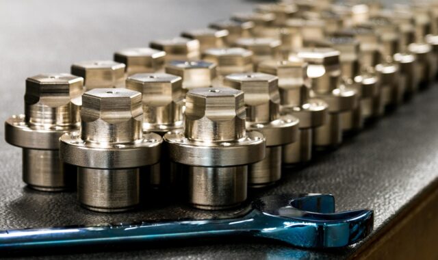
High precision components and the controls that make tight tolerances reliable
What high precision components really require
High precision components are parts whose function depends on controlled geometry, surface condition, material behavior, and repeatable measurement. They are not defined only by small tolerance numbers on a drawing. In mechanical manufacturing, the practical question is whether a component can be produced repeatedly, inspected credibly, and assembled without hidden adjustment or rework. Common standards used to frame this control include ISO 1101:2017 for geometrical product specifications, ASME Y14.5-2018 for GD&T practice, ISO 9001:2015 for quality management systems, ISO/IEC 17025:2017 for competent testing and calibration laboratories, and NIST guidance on metrological traceability.
The main lesson is simple: a tighter number does not automatically create a better part. If the datum structure, inspection method, material stability, thermal conditions, machine capability, or communication between design and production is weak, tighter tolerances may add cost while increasing the risk of dispute. For related manufacturing topics, see the precision components section.

Why precision is not the same as accuracy
In everyday language, precision and accuracy are often used as if they mean the same thing. In manufacturing, the distinction matters. Accuracy describes how close a result is to the intended value. Precision describes how closely repeated results agree with each other. A turning process can be precise but offset from the nominal size, or accurate on one part but unstable across a batch. High precision components need both controlled centering and controlled variation.
This is why a reliable specification should start with the functional requirement. A shaft diameter may matter because it affects fit, bearing life, lubrication, or torque transfer. A flatness tolerance may protect sealing performance. A perpendicularity tolerance may protect alignment across an assembly. When the functional reason is clear, the tolerance can be placed where it creates value instead of being spread across every dimension.
Dimensional limits alone may not describe the part well enough. Geometric tolerancing is used because many failures are related to form, orientation, location, and run-out. ISO 1101 defines the symbol language for geometrical specification of workpieces, while ASME Y14.5 is widely used as an authoritative GD&T reference in drawings and contracts. For buyers and engineers, the selected system should be stated clearly. Mixing assumptions from different drawing practices can lead to avoidable disagreement during inspection.
Design controls that reduce manufacturing ambiguity
A high precision component should begin with a clear definition of what must be controlled and what may vary. Over-specification is common when teams try to protect performance by tightening many unrelated dimensions. Under-specification is just as risky when a drawing controls size but ignores orientation, position, or surface condition. The better approach is to connect each critical tolerance to a function, mating feature, assembly sequence, or measurement plan.
Datum strategy
Datums are the reference structure that make inspection and assembly meaningful. If a part is inspected from one surface but assembled from another, a good inspection report may not predict field performance. For high precision components, datum features should normally reflect how the part is located in the assembly, how loads pass through it, or how tooling and inspection fixtures will hold it. A stable datum strategy also helps suppliers design fixtures and reduces the chance that two laboratories measure the same part differently.
Tolerance stack-up
Critical assemblies rarely fail because of one dimension alone. Variation accumulates across mating parts, fasteners, clearances, coatings, heat treatment distortion, and assembly sequence. Tolerance stack-up analysis helps identify which features deserve tight control and which can remain less restrictive. This is especially important where multiple precision components interact, such as linear motion systems, rotating assemblies, valve bodies, connectors, and miniature mechanical devices.
Surface and edge requirements
High precision components often fail at surfaces and edges rather than at nominal dimensions. Burrs can change assembly force, interfere with seals, or introduce contamination. Surface roughness can affect friction, fatigue, leakage, coating adhesion, and wear. Sharp edges, chamfers, radii, and deburring notes should be practical enough for both production and inspection. A vague note such as remove all burrs may be insufficient when edge condition is functionally critical.
Process variables that decide repeatability
Once the drawing is stable, process control determines whether precision can be held economically. CNC machining, grinding, electrical discharge machining, precision stamping, laser processing, additive manufacturing, and finishing can all produce accurate parts in the right context. The key question is not which process sounds most advanced. It is which process can hold the required features across material lots, tool wear, thermal drift, and production volume.
Material behavior is a major variable. Aluminum, stainless steel, titanium alloys, copper alloys, engineering plastics, and hardened steels respond differently to cutting forces, heat, residual stress, and finishing. Thin walls may move after clamping is released. Heat treatment may distort previously machined features. Plating, anodizing, passivation, polishing, or coating can change dimensions and surface properties. For this reason, drawings should state whether dimensions apply before or after finishing when that distinction affects acceptance.
Machine condition and environment also matter. Precision machining is sensitive to spindle condition, tool runout, fixturing stiffness, coolant strategy, vibration, and temperature. A small workshop can sometimes produce exceptional prototypes, but repeatable production requires documented setup control, tool life rules, in-process checks, and reaction plans when variation trends toward a limit. ISO 9001:2015 does not prescribe one manufacturing method, but it establishes a quality management framework for controlling processes, addressing requirements, and improving consistency.
Digital information flow is becoming more important. NIST work on digital thread and model-based enterprise highlights the role of product-definition standards such as STEP, QIF, and MTConnect in linking design, manufacturing, and quality data. For high precision components, the value is not technological fashion. The value is reducing interpretation gaps between CAD models, CAM programs, inspection plans, and production feedback.
Inspection, traceability, and measurement uncertainty
Inspection is not just the final gate before shipment. It is part of the manufacturing system. A part can only be accepted with confidence when the measurement method is suitable for the tolerance being judged. Coordinate measuring machines, optical systems, laser scanners, surface roughness testers, air gauges, thread gauges, micrometers, bore gauges, and functional fixtures all have strengths and limits. The method should match the feature geometry, tolerance size, surface condition, and production rate.
NIST defines metrological traceability as a property of a measurement result connected to a reference through a documented unbroken chain of calibrations, with each link contributing to measurement uncertainty. The practical implication is important: a calibrated instrument alone does not automatically make every result traceable. The measurement result still needs a defined method, calibration status, uncertainty consideration, environmental control where relevant, and records that support the claim. See also: buying guides.
ISO/IEC 17025:2017 is the international standard used for testing and calibration laboratories to demonstrate competence, impartiality, and consistent operation. In supplier evaluation, an ISO/IEC 17025 calibration certificate can be meaningful, but it should still be checked for scope, measurement range, uncertainty, and relevance to the instrument or feature being measured.
| Control area | Why it matters for high precision components | Practical check |
|---|---|---|
| Drawing interpretation | Prevents disagreement over datums, symbols, and acceptance rules | Confirm the GD&T standard and revision used |
| Measurement uncertainty | Reduces false accept or false reject decisions near tolerance limits | Review method suitability for critical features |
| Calibration traceability | Connects measurement results to recognized references | Check calibration certificates, intervals, and scope |
| Process capability | Shows whether production can hold variation repeatedly | Use in-process data for critical characteristics |
| Change control | Protects performance when tools, materials, fixtures, or finishing change | Define approval rules for significant process changes |
How to evaluate a production plan for high precision components
A useful production review connects design intent, manufacturing route, inspection method, and acceptance evidence. Buyers often focus on unit price, lead time, and material grade, but precision risk usually sits in details that are less visible at the quotation stage. The following questions help expose those risks before production begins.
- Which features are truly critical? Identify dimensions, geometric tolerances, surfaces, and edges that affect function, safety, wear, sealing, alignment, or assembly.
- What process will create each critical feature? A roughing operation, finishing pass, grinding step, honing operation, or post-treatment process may each affect final conformity.
- When will inspection occur? Some features should be checked in process, some after finishing, and some after stabilization or cleaning.
- How will the part be held? Fixturing affects both machining and measurement. Clamping distortion can make a part look correct while held and nonconforming after release.
- What happens when results approach the tolerance limit? A reaction plan should define tool adjustment, machine offset control, segregation, reinspection, and escalation.
- How are revisions controlled? Precision components are vulnerable to small drawing changes, model updates, material substitutions, and undocumented finishing changes.
The same logic applies when comparing manufacturing routes. CNC milling may be flexible for complex shapes, grinding may be necessary for tight cylindrical or flatness requirements, EDM may suit hard materials and internal features, and additive manufacturing may be useful for complex geometries that require later machining on critical interfaces. The right route depends on feature function, material, volume, tolerance, surface requirement, and verification plan.
Common failure modes and practical safeguards
Many precision failures are not dramatic. They appear as slow assembly, inconsistent fit, excessive adjustment, premature wear, leakage, vibration, noise, or inspection disputes. These issues often come from a gap between the drawing and the real production system.
One common failure mode is treating prototype success as proof of production stability. A prototype may be produced by a senior machinist with extra measurement and manual correction. Production requires a controlled method that can survive shift changes, tool changes, material lot variation, and schedule pressure. Another failure mode is accepting a certificate of conformance without reviewing how critical features were measured. A report with many dimensions is not automatically strong evidence if the most important features were checked with unsuitable equipment or unclear datums.
Thermal effects are another source of error. Metals expand and contract with temperature, and precision measurement can be sensitive to shop-floor conditions. For tight tolerances, the inspection environment, part temperature, and stabilization time may need attention. Cleanliness is also practical, not cosmetic. Chips, oil film, polishing residue, burr fragments, or coating buildup can affect measurement and assembly.
The safeguards are familiar but often underused: functional tolerance review, early supplier discussion, first article inspection for critical features, in-process control for unstable characteristics, documented calibration, clear revision history, and defined acceptance criteria for surfaces and edges. These controls do not remove all variation, but they make variation visible before it becomes an assembly or field problem.
Frequently asked questions
What qualifies a part as a high precision component?
A part may be considered high precision when its performance depends on tight control of size, geometry, surface condition, material state, or measurement confidence. There is no single universal tolerance threshold. A tolerance that is demanding for one material, feature size, or process may be ordinary for another.
Are tighter tolerances always better?
No. Tighter tolerances should be used when they protect function, interchangeability, life, safety, or assembly efficiency. Unnecessary tightening can increase machining time, inspection cost, scrap risk, supplier disagreement, and lead time without improving the product.
Why is GD&T important for high precision components?
GD&T helps define allowable variation in form, orientation, location, and run-out relative to datums. This matters because many precision problems are geometric rather than simple size errors. A clear GD&T scheme helps design, manufacturing, and inspection teams evaluate the same functional requirement.
What should be included in an inspection plan?
An inspection plan should identify critical characteristics, datum setup, equipment, measurement method, calibration status, sampling approach, environmental requirements where relevant, and records needed for acceptance. For very tight tolerances, measurement uncertainty should be considered before accepting or rejecting borderline results.
How can buyers reduce risk when sourcing high precision components?
Buyers can reduce risk by sharing complete drawings and models, clarifying the applicable GD&T standard, identifying critical features, requesting a realistic control plan, reviewing first article evidence, and controlling revisions. The most reliable sourcing discussions focus on function and verification, not only on nominal tolerance values.