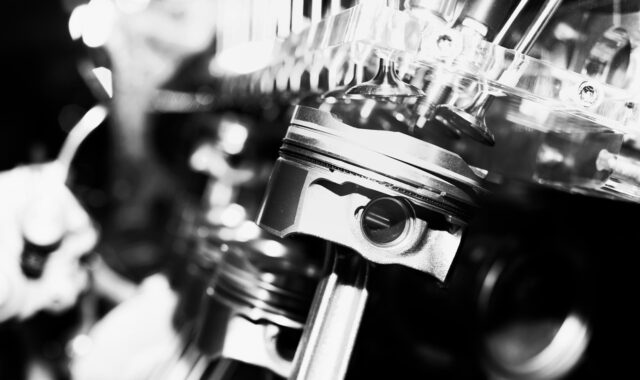
How precision mold components affect tolerance, uptime, and maintenance
Why precision mold components carry more risk than their size suggests
Precision mold components are the locating, guiding, forming, cooling, venting, sliding, and ejection elements that let a mold repeat the same motion and produce the same geometry over many cycles. Their individual size may be small, but their effect is cumulative. A worn guide bushing, a core pin with poor concentricity, or an ejector sleeve with the wrong clearance can lead to flash, drag, pin marks, dimensional drift, or unplanned downtime.
For buyers, designers, and maintenance teams, the practical question is not simply whether a component is “precise.” The question is whether its material, fit, tolerance, surface condition, and replacement strategy match the mold’s production duty, resin, cycle conditions, and maintenance access.
For more related manufacturing topics, see the precision components category.
The component groups that control repeatability
Public catalogs from mold component suppliers such as DME, MISUMI, HASCO, and Meusburger commonly group mold hardware by function. That structure is useful because mold performance is not controlled by one part alone. Alignment, forming, motion, thermal control, venting, and ejection all need to work together.
| Component group | Main function | Typical precision risk | Review point |
|---|---|---|---|
| Guide pins and bushings | Align the fixed and moving mold halves | Wear, misalignment, galling, uneven closing | Fit, lubrication method, hardness pairing, replacement interval |
| Core pins, cavity inserts, and sleeves | Form holes, bosses, ribs, and detailed geometry | Concentricity error, deflection, surface damage, sticking | Datum control, surface finish, polishing direction, material stability |
| Ejector pins, blades, and sleeves | Release the molded part or runner system | Pin marks, bending, seizure, uneven ejection force | Pin location, bearing length, clearance, return confirmation |
| Slides, lifters, and angular pins | Release undercuts or side features | Side-load wear, timing error, locking damage | Travel, locking angle, wear plates, lubrication access |
| Sprue bushings, gates, and runner components | Control melt entry into the mold | Leakage, wear, gate vestige variation, poor sealing | Nozzle fit, heat exposure, material compatibility |
| Cooling and venting components | Manage heat and allow trapped gas to escape | Warpage, burn marks, corrosion, blocked vents | Cooling circuit access, sealing, vent depth policy, cleaning method |
This is why a specification that lists only nominal dimensions is incomplete. Precision also depends on how parts move against each other, how they are lubricated, how heat changes their fit, and how easily they can be inspected or replaced during maintenance.
How component precision becomes molded part quality
In injection molding, the molded part is affected by tooling accuracy, resin behavior, processing conditions, cooling balance, and part geometry. ISO 20457:2026, published in August 2026, addresses tolerances and acceptance conditions for plastic molded parts. A useful takeaway from that standard is that plastics need a plastics-specific tolerance approach because molded dimensions can be influenced by shrinkage, warpage, non-uniform cooling, and material behavior. In other words, a precise mold is necessary, but it does not automatically guarantee a tight molded part tolerance without process control.
Precision mold components influence molded part quality in several direct ways. Alignment components affect parting-line consistency and shutoff quality. Core pins and inserts affect internal features such as holes, clips, bosses, and ribs. Ejection components affect visible marks, deformation, and release consistency. Cooling components affect cycle stability and dimensional repeatability. Venting components affect burns, short shots, and trapped gas defects.
The practical point is that component accuracy should be evaluated as part of a system. If a molded part has a dimensional issue, replacing a core pin may help when the root cause is pin wear or location error. If the larger cause is uneven cooling, resin shrinkage variation, or press setup, the same replacement may not solve the problem. A disciplined review separates tooling facts from process assumptions.
Specification details buyers should define before sourcing
Material and heat treatment
Material choice should reflect the component’s role. A sliding component needs wear resistance and a compatible running surface. A forming insert may need polishability, corrosion resistance, or dimensional stability after heat treatment. An ejector pin needs enough toughness to avoid bending while resisting wear at the bearing surface. The purchase specification should state the material grade or approved equivalent, heat treatment requirement, and any certificate expectations. Vague wording such as “tool steel pin” leaves too much room for variation.
Fit, tolerance, and datum control
For precision mold components, the controlling dimension is often not the largest dimension. A small diameter, shoulder, flat, head thickness, or datum face can determine whether the component locates correctly. Drawings should identify functional datums, critical fits, perpendicularity requirements, concentricity or runout needs, and the inspection method. This is especially important for core pins, stepped ejector pins, sleeves, and inserts that interact with multiple plates.
Surface finish and coating
Surface finish affects release, wear, and lubrication retention. A highly polished surface may help release on a forming area, while a sliding area may need a finish that supports controlled lubrication. Coatings can reduce friction or improve wear resistance, but they also change dimensions and may require different clearances. If a coating is specified, the drawing should state whether final dimensions apply before or after coating.
CAD data and interchangeability
Many standard component systems provide CAD data and catalog dimensions. That helps designers reduce drafting time and supports replacement planning. However, interchangeability still depends on the exact standard, revision, material, and fit class selected. A component described only as “DME style” or “HASCO type” may not be enough for procurement. The purchasing record should identify the actual catalog family, drawing number, or controlled internal part number.
Standard components vs custom precision components
Standard mold components are widely used because they reduce design time, shorten procurement cycles, and simplify replacement. Catalog systems usually cover common items such as ejector pins, sleeves, leader pins, bushings, locating rings, sprue bushings, slides, wear plates, return pins, and cooling fittings. For many molds, standard parts are the most practical choice.
Custom precision components are justified when mold geometry, production volume, resin, surface requirements, or the motion sequence cannot be handled by catalog hardware. Examples include non-round core pins, shaped sleeves, special vent inserts, high-wear slides, medical or optical forming inserts, and components that combine multiple functions in limited space. See also: buying guides.
| Choice | Advantages | Limitations | Best fit |
|---|---|---|---|
| Standard components | Faster sourcing, known dimensions, easier replacement, CAD availability | Limited geometry, possible mismatch with unusual mold layouts | Common mold structures and predictable wear parts |
| Modified standard components | Balances availability with mold-specific adjustment | Requires control of post-machining and heat-affected areas | Length changes, flats, simple reliefs, minor fit adaptation |
| Custom components | Can match unique geometry, motion, or performance requirements | Longer lead time, higher documentation burden, harder replacement | Critical forming details, complex undercuts, special release or wear conditions |
The decision should be based on risk rather than habit. If a standard pin is inexpensive but causes repeated downtime, the apparent saving disappears quickly. If a custom insert adds cost without improving fit, durability, or part quality, it may add unnecessary complexity.
Inspection and maintenance signals to watch
Precision mold components usually show early warning signs before a major failure. Flash near the parting line can point to alignment wear, insufficient locking, or shutoff damage. New ejector marks can indicate pin wear, bent pins, poor return, excessive ejection force, or part sticking. Scratches on molded surfaces can point to damaged forming inserts or trapped contamination. Uneven drag in slides or lifters may suggest lubrication loss, wear plate damage, or side-load problems.
Maintenance records are most useful when they connect symptoms to component condition. Instead of recording only “mold cleaned,” the record should note which pins were polished, which vents were cleaned, which bushings showed wear, and whether any component was replaced. Over time, this creates a practical wear map. It can reveal whether a mold has a recurring design issue, a lubrication problem, a process condition that accelerates wear, or a component sourcing inconsistency.
Inspection should also include storage and handling. Precision components can be damaged before installation through corrosion, impact, poor packaging, or mixing similar but non-identical parts. Small differences in shoulder length, head thickness, or coating can matter. Clear labeling and controlled storage reduce mistakes during urgent repairs.
A practical procurement and design review checklist
Before ordering or approving precision mold components, teams can reduce risk by reviewing a short checklist:
- Confirm the component function, not only its name.
- Identify critical dimensions, datums, fits, and movement surfaces.
- Specify material, heat treatment, coating, and inspection requirements.
- Check whether final dimensions apply before or after coating.
- Confirm compatibility with the mold standard system being used.
- Define acceptable substitutions before the order is placed.
- Request certificates or inspection reports when the part is critical to safety, medical use, dimensional capability, or high-volume production.
- Plan replacement access for wear components such as pins, sleeves, bushings, and slides.
- Record maintenance findings so future sourcing decisions are based on evidence.
This checklist does not replace detailed engineering review, but it helps close common gaps between design intent, purchasing language, machining, inspection, and toolroom maintenance.
Frequently asked questions
What are precision mold components?
Precision mold components are accurately made mold parts that guide, locate, form, cool, vent, move, or eject within a mold assembly. Common examples include guide pins, bushings, core pins, cavity inserts, ejector pins, sleeves, lifters, slides, sprue bushings, locating rings, wear plates, and vent inserts.
Are standard mold components precise enough?
Often, yes. Standard components can be a reliable choice when their dimensions, material, and fit match the mold design. They become risky when a buyer assumes that parts from different standards or suppliers are automatically interchangeable. Critical applications should define the exact catalog series, drawing, and inspection requirement.
How do mold components affect molded part tolerances?
They affect alignment, feature location, release, cooling, and repeatability. However, molded part tolerance is also influenced by resin behavior, shrinkage, processing conditions, and part design. A precise component can reduce tooling-related variation, but it cannot remove all process-related variation.
When should ejector pins or bushings be replaced?
Replacement should be considered when inspection shows wear, bending, scoring, seizure, excessive clearance, return problems, or repeated part defects linked to ejection. A fixed schedule may help high-volume molds, but condition-based maintenance is usually more accurate when supported by good records.
What should be included in a precision mold component drawing?
A strong drawing should include functional datums, critical dimensions, tolerances, material, heat treatment, surface finish, coating notes, inspection points, and revision control. For sourced parts, it should also reference the approved standard or internal part number.