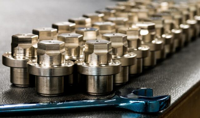
Precision machined components and the real cost of tight tolerances

What precision machined components mean in real production
Precision machined components are parts produced by controlled material removal, typically on CNC mills, lathes, mill-turn centers, grinders or electrical discharge machining equipment, to meet defined dimensional, geometric and surface requirements. In production, precision does not come from the machine alone. It depends on the full system: a clear drawing or model, suitable material, a stable machining process, controlled conditions, trained operators, calibrated inspection equipment and agreed acceptance rules. A part can meet a very tight size tolerance and still create problems if the datum scheme, surface texture, burr control or measurement method is unclear. For engineers, buyers and manufacturing teams, the practical question is not only how tight a tolerance can be held, but which tolerances are needed for function and how they will be verified repeatably.
In mechanical manufacturing, precision becomes important when parts must assemble with little adjustment, seal under pressure, rotate with low vibration, locate other parts accurately, resist wear or maintain performance across repeated production lots. Common examples include shafts, housings, bushings, manifolds, mounting plates, valve bodies, aerospace brackets, medical instrument parts and automation tooling components. These parts may look straightforward, but small changes in flatness, concentricity, perpendicularity, hole position or surface finish can affect assembly quality and service life.

For more related manufacturing topics, visit the precision components section.
Why tolerance decisions drive cost, not just accuracy
Tolerances are often treated as a small note on a drawing, but on the shop floor they influence almost every major cost driver. A tighter tolerance may require slower cutting parameters, additional finishing passes, more stable fixturing, higher-grade tooling, in-process inspection, temperature control, extra cleaning, more detailed documentation or specialized measuring equipment. The cost increase is not always linear. Moving from a moderate tolerance to a very tight tolerance can change the process route entirely.
This is why precision machined components should be specified around function rather than habit. If a bore only provides clearance for a fastener, a very tight diameter tolerance may add cost without improving performance. If a bearing seat controls rotation, tight size, roundness and surface texture requirements may be essential. A strong specification separates critical-to-function features from general features and avoids applying the same tight tolerance across the whole part.
| Specification choice | Likely production effect | Practical question to ask |
|---|---|---|
| Very tight linear tolerance | May require finishing passes, tool wear control and more inspection | Does this dimension directly affect fit, alignment or performance? |
| Tight positional tolerance | Requires a stable datum system, accurate fixturing and reliable CMM strategy | Are the datums functional and accessible for inspection? |
| Low surface roughness value | May require grinding, honing, lapping or controlled cutting conditions | Is the surface sealing, sliding, bearing or cosmetic? |
| Strict flatness or parallelism | May require stress relief, balanced machining or additional inspection setups | Will material movement after roughing be controlled? |
| Unspecified burr limits | Can cause inconsistent finishing and assembly risk | Which edges are functional, sealing, handled or safety related? |
The most useful drawing is not necessarily the one with the tightest numbers. It is the one that communicates the part’s functional priorities clearly. That clarity helps manufacturing teams choose suitable processes and helps inspection teams confirm the part without relying on assumptions.
Specifications that prevent confusion before machining starts
Many quality problems begin before the first chip is cut. Ambiguous drawings, incomplete models and unclear acceptance criteria can lead to different interpretations between design, machining and inspection teams. Standards such as ASME Y14.5 and ISO GPS systems exist because dimensional requirements must be communicated in a consistent way. In practice, the main issue is not simply naming a standard, but applying it correctly and making sure all parties understand the drawing basis.
Datums and GD&T should reflect part function
Geometric dimensioning and tolerancing is useful because it defines how features relate to one another. A hole pattern, for example, may need to be controlled relative to mounting faces rather than to an arbitrary edge. A shaft may require runout control relative to bearing journals. A housing may require perpendicularity between a bore and a mounting surface. When datums are chosen from functional surfaces, the inspection setup is more likely to match how the part is assembled.
Poor datum selection can make a part appear acceptable during inspection but troublesome in assembly. It can also force the shop to hold a nonfunctional surface too tightly while the real functional relationship remains underdefined. For complex precision machined components, datum planning should be reviewed early, especially when multiple operations, multiple setups or post-machining treatments are involved.
Surface texture needs more than a single roughness value
Surface finish affects sealing, lubrication, friction, coating adhesion, fatigue behavior and appearance. A single roughness value, however, does not always describe the functional requirement. A sealing face, a sliding guide and a painted cover may all have different needs even if their dimensional tolerances look similar. The drawing should identify which surfaces require controlled texture and which can follow a general finish requirement.
It is also important to define whether machining marks, scratches, dents or tool transition marks are acceptable. Without that clarity, finishing becomes subjective. For precision components used in assemblies, edges and transitions matter as much as broad surfaces. Burrs near ports, grooves, O-ring seats, threads or small holes can affect cleanliness, flow, sealing and handling safety.
Manufacturing variables that affect repeatability
Precision machining is a controlled process, but it is not static. A program that produces a good first article may drift as tools wear, material lots change, coolant condition changes or machine temperature stabilizes. Repeatability depends on understanding these variables and controlling the ones that matter most for the part.
- Material behavior: Aluminum, stainless steel, titanium, brass, engineering plastics and alloy steels respond differently to cutting heat, clamping pressure and residual stress. Thin walls, asymmetric shapes and high material removal rates increase the risk of distortion.
- Workholding: A rigid fixture can improve repeatability, but excessive clamping force can deform delicate parts. For thin or flexible components, support strategy is often as important as toolpath strategy.
- Tool wear: Cutting edges change during production. Wear can affect hole size, surface finish, burr formation and tool pressure. Critical features may need defined tool life limits rather than waiting for visible failure.
- Thermal effects: Machine structure, cutting heat and shop temperature can influence dimensional results, especially on larger parts or tight tolerance features.
- Operation sequence: Roughing, stress relief, semi-finishing and finishing may be needed when material movement is expected. Finishing a critical feature too early can create risk if later operations release stress.
For buyers, the lowest quoted machining time does not always represent the lowest production risk. For engineers, a drawing should leave room for a practical process route unless a specific process is required for function. For manufacturers, process planning should consider the full lot, not only the first approved piece.
Inspection planning and measurement uncertainty
Inspection is often viewed as the final step, but for precision machined components it should be planned together with the manufacturing process. A feature cannot be managed well if it cannot be measured reliably. National metrology organizations such as NIST have long emphasized the role of dimensional metrology, measurement traceability and uncertainty in manufacturing quality. ISO 14253-1 also addresses decision rules for proving conformity or nonconformity when measurement uncertainty is involved.
The practical lesson is simple: when a measurement result is close to a tolerance limit, the measurement system matters. Probe choice, fixture repeatability, part cleanliness, temperature, sampling strategy, calibration status and software evaluation method can all influence the result. A coordinate measuring machine can be powerful, but it is not automatically the right answer for every feature. Some features are better checked with air gauges, bore gauges, optical systems, surface testers, thread gauges or dedicated functional gauges. See also: buying guides.
| Inspection item | Why it matters | Common risk if ignored |
|---|---|---|
| Datum setup | Aligns measurement with design intent | Part passes inspection but fails assembly |
| Gauge capability | Confirms the instrument is suitable for the tolerance | Good parts rejected or bad parts accepted |
| Surface cleanliness | Prevents chips, oil or burrs from affecting readings | False dimensional or surface finish results |
| Sampling plan | Defines how much of the lot is checked | Process drift is missed between inspections |
| Measurement conditions | Controls temperature and handling effects | Inconsistent results between supplier and customer |
A strong inspection plan also defines the required documentation. First article reports, dimensional layouts, material certificates, surface finish records, heat treatment records and coating certificates may be necessary for some industries. For general industrial components, a simpler inspection record may be sufficient. The right level depends on risk, industry requirements and the role of the part in the final assembly.
A practical checklist before ordering or releasing a drawing
Before releasing a precision machined component for production, a short technical review can prevent many avoidable problems. The goal is not to make the drawing longer. The goal is to make the important requirements unmistakable.
- Identify which dimensions and geometric controls are critical to function.
- Use GD&T where relationships between features matter more than isolated plus-minus dimensions.
- Choose datums that match assembly function and can be repeated during inspection.
- Avoid unnecessarily tight default tolerances on noncritical features.
- Specify material grade, condition and any required heat treatment or stress relief.
- Define surface finish only where it affects sealing, sliding, wear, fatigue, coating or appearance.
- Clarify edge break, deburring and cleanliness expectations near functional features.
- Consider whether plating, anodizing, passivation, coating or heat treatment will change final dimensions.
- Confirm that the required inspection method is practical for the feature size, tolerance and geometry.
- State documentation requirements clearly instead of assuming a default report format.
This checklist is especially useful when a part moves from prototype to production. Prototype machining often depends on skilled interpretation and close communication. Production requires repeatable instructions. If a prototype drawing contains vague notes, missing datums or broad assumptions, those gaps usually become more expensive when quantities increase.
How to balance precision, lead time and manufacturability
The central trade-off in precision machining is not precision versus quality. It is uncontrolled precision versus purposeful precision. A well-designed component gives tight control to the features that matter and reasonable freedom to the features that do not. That balance can reduce scrap, shorten lead time and improve communication without weakening the final product.
Early design-for-manufacturing review is the most reliable way to find that balance. For example, a manufacturer may suggest changing an internal corner radius to match a standard tool, adding relief to improve access, adjusting wall thickness to reduce distortion or changing a tolerance from a linear dimension to a positional control. These changes do not necessarily reduce performance. In many cases, they make the functional requirement easier to achieve consistently.
Precision machined components perform well when design, machining and inspection are treated as connected decisions. Tight tolerances can be valuable, but only when they are tied to function, supported by a stable process and verified by a suitable measurement method. That is where precision becomes more than a number on a drawing.
Frequently asked questions
What makes a machined component a precision component?
A machined component is usually considered precision work when its function depends on controlled dimensions, geometry, surface texture and repeatability. The label should be based on the part’s requirements, not simply on the use of CNC equipment.
Are tighter tolerances always better?
No. Tighter tolerances are better only when they improve fit, function, safety, durability or inspection confidence. Unnecessary tight tolerances can increase cost, lead time and rejection risk without improving the final assembly.
Why is GD&T important for precision machined components?
GD&T helps define relationships between features, such as position, flatness, perpendicularity, runout and profile. This matters when assembly performance depends on how features relate to datums rather than on isolated dimensions.
Which inspection method is best for precision parts?
There is no single best method for every feature. CMMs, optical systems, surface testers, bore gauges, air gauges and functional gauges can all be appropriate depending on tolerance, geometry, surface access and production volume.
What should be reviewed before moving from prototype to production?
Review critical features, datums, tolerances, materials, finishing operations, burr control, inspection methods and documentation requirements. A prototype can succeed through close attention, but production needs clear and repeatable instructions.