DFM design for manufacturing checklist for mechanical parts

What DFM means in mechanical manufacturing
DFM design for manufacturing is the practice of designing a part, assembly, and engineering definition so they can be produced repeatably at the required cost, quality level, and production volume. In mechanical manufacturing, DFM is not a final drawing check. It is a design discipline that connects geometry, material choice, tolerances, tooling, workholding, assembly, inspection, and supplier capability before costly commitments are made.
The value of DFM is mainly early risk reduction. A feature that looks simple in CAD may still require a special cutter, a deep mold slide, a secondary operation, a difficult fixture, excessive inspection time, or a tolerance that the intended process cannot hold economically. Good DFM does not dilute product function. It asks whether the same function can be achieved with fewer fragile features, clearer specifications, simpler tooling, and a more stable manufacturing route.
For more articles on process selection, machining, molding, casting, and production planning, visit the manufacturing processes section.
Why DFM should start before detailed drawings
Many manufacturing costs become difficult to change once the concept, material, interface dimensions, and joining method are fixed. A Design Society publication on early cost estimation summarized a common product development finding: a large share of product cost is committed during the conceptual and early design stages, even though the exact purchase price is usually known later. The practical lesson is clear. If manufacturability is reviewed only after the drawing is complete, the team may be left with expensive rework instead of low-cost design choices.
Early DFM also reduces the gap between engineering intent and shop-floor execution. NIST has discussed digital-thread work in terms of connecting design, manufacturing, inspection, and product support information. For DFM, the same logic applies at project level: the design file, drawing, process plan, inspection method, and supplier feedback should not sit in separate worlds. When manufacturing knowledge feeds back into the design, teams can catch avoidable problems earlier.
A useful DFM review answers five questions before release: Can the selected process make the feature repeatably? Are the tolerances tied to function rather than habit? Can the part be held, cut, formed, molded, cast, cleaned, coated, and inspected? Can the assembly be built without hidden access problems? Can suppliers quote the work without guessing?
A practical DFM checklist for mechanical parts
The checklist below applies to machined, sheet metal, molded, cast, and fabricated mechanical parts. Exact limits vary by material, supplier equipment, production volume, and quality requirements, but the review questions are broadly useful.
| DFM review area | What to check | Common risk if ignored |
|---|---|---|
| Process fit | Match geometry, volume, material, and tolerance needs to machining, casting, molding, forming, additive manufacturing, or fabrication. | The design is quoted with unnecessary secondary operations or rejected as impractical. |
| Material | Confirm machinability, formability, shrinkage, weldability, heat treatment response, coating compatibility, and supply availability. | The nominal material works on paper but causes tool wear, distortion, cracking, or long lead times. |
| Geometry | Review wall thickness, radii, pockets, ribs, bosses, draft, undercuts, hole depth, corner access, and tool reach. | Features require special tooling, complex molds, poor chip evacuation, or unstable forming. |
| Tolerances | Separate functional tolerances from default title-block tolerances and avoid over-controlling noncritical features. | Inspection cost rises and yield falls without improving product performance. |
| Assembly | Check part count, orientation, fastener access, alignment features, joining sequence, service access, and mistake-proofing. | Operators need extra fixtures, rework, or manual adjustment to build the assembly. |
| Inspection | Confirm datums, measurement access, gauge strategy, surface requirements, and acceptance criteria. | Manufacturing can make the part, but quality cannot verify it consistently. |
Process-specific DFM factors
CNC machining
For CNC machined parts, manufacturability is often driven by tool access, setup count, workholding, material removal, and tolerance stack-up. Deep narrow pockets, very small internal radii, thin unsupported walls, and long small-diameter holes usually increase risk. Designers can often reduce cost by using radii that match standard cutters, avoiding unnecessary cosmetic machining on hidden surfaces, designing datums that match practical fixturing, and keeping critical features accessible from fewer setups.
Flatness, parallelism, and positional tolerances should relate to how the part is located in the final assembly. If a tight tolerance is inherited from an older design or applied as a blanket default, it may add cost without adding function. ASME describes Y14.5 as the authoritative U.S. standard language for geometric dimensioning and tolerancing. Its DFM value is clarity: it helps communicate what must be controlled and how the drawing should be interpreted.
Sheet metal and fabricated parts
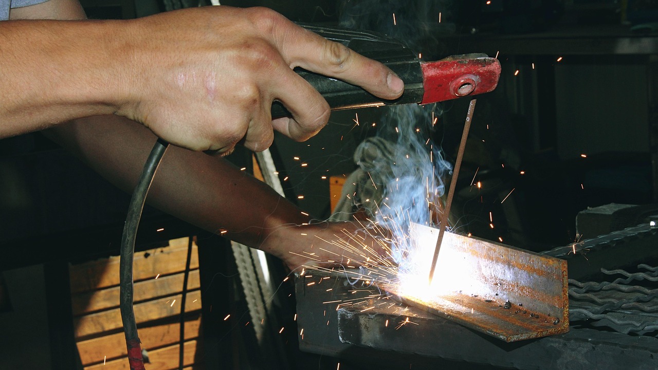
Sheet metal DFM focuses on bend radius, bend relief, hole-to-bend distance, grain direction where relevant, flat pattern development, welding distortion, and coating access. Features that are easy to model may be difficult to bend if they collide with tooling or sit too close to bend lines. Assemblies that look rigid in CAD may move during welding unless the design accounts for joint design, tack sequence planning, and inspection datums.
For fabricated frames, brackets, and enclosures, DFM should also consider whether slots, tabs, and self-locating features can reduce fixture complexity. This is not only a cost issue. Better location features can improve repeatability and reduce reliance on manual measurement during fit-up.
Injection molding and casting
Molded and cast parts need early review because tooling decisions can lock in cost and lead time. Wall thickness transitions, ribs, bosses, draft, gate location, parting line, undercuts, ejection surfaces, sink marks, shrinkage, and warpage are central DFM topics. A thick section may appear stronger in CAD but create sink or cooling problems in molding. A sharp internal corner may create stress concentration and poor fill. A small undercut may require a slide, lifter, insert, or secondary operation.
DFM for these processes is also sensitive to volume. A tooling feature that is excessive for a prototype may be justified for high-volume production, while a design optimized for prototype machining may be uneconomical when transferred to molding or casting. For that reason, the DFM review should include expected production quantity, not only the prototype requirement.
Additive manufacturing
Additive manufacturing does not remove the need for DFM; it changes the questions. Designers still need to consider build orientation, support removal, anisotropic properties, surface finish, thermal distortion, powder or resin removal, post-machining, and inspection. Additive processes can simplify assemblies and produce complex internal geometry, but unsupported cost-reduction claims should be treated carefully. The part must be evaluated against the real production route, not the most flexible prototype route.
Tolerances, GD&T, and inspection in DFM
Tolerancing is one of the most important DFM levers because it directly affects process capability, inspection time, scrap, and supplier interpretation. A good DFM review does not simply loosen every tolerance. It identifies which features control function, sealing, alignment, motion, load transfer, safety, or interchangeability, then gives those features clear and measurable requirements.
GD&T can support manufacturability when it is used to express function rather than decorate a drawing. Datums should reflect how the part is assembled, used, or inspected. Feature control frames should avoid ambiguity. Profile tolerances can sometimes describe complex surfaces more clearly than many coordinate dimensions, while positional tolerances can better represent hole patterns that interact with fasteners or pins. Poor GD&T, however, can be worse than no GD&T if manufacturing and inspection teams cannot interpret it consistently. See also: buying guides.
International work often uses ISO geometrical product specification standards. ISO 20170:2019, for example, addresses decomposition of geometrical characteristics for manufacturing control. The larger DFM point is not that every project needs the same standard, but that drawings and model-based definitions should use a recognized specification system and name the applicable revision. If a requirement cannot be measured reliably, it is not a stable manufacturing requirement.
DFM, DFA, DFMA, and design-to-cost are related but not identical
DFM is often discussed with DFA, DFMA, and design-to-cost. The terms overlap, but they should not be used as if they mean the same thing.
- DFM focuses on whether individual parts and features can be manufactured efficiently and consistently.
- DFA focuses on reducing assembly effort through part count reduction, easier handling, clearer orientation, and simpler joining.
- DFMA combines design for manufacture and design for assembly into a broader review of product structure and production effort. Boothroyd Dewhurst popularized this methodology and treats manufacturing and assembly as connected cost drivers.
- Design-to-cost starts with a target cost and drives design decisions toward that target, often using cost models, supplier input, and trade-off analysis.
In practice, a robust mechanical design review uses all four perspectives. A machined bracket may be easy to produce by itself but still perform poorly from a DFMA perspective if it requires many fasteners and difficult alignment. A molded housing may reduce assembly time but fail DFM if the wall design creates sink and warpage. Design-to-cost can guide trade-offs, but it should not override safety, function, compliance, or quality requirements.
How to run a useful DFM review
A DFM review is most effective when it is structured, cross-functional, and specific to the chosen manufacturing route. A practical workflow has four stages.
- Concept review: Compare candidate processes, major materials, part count, joining methods, expected volume, and critical functions. At this point, changes are still relatively inexpensive.
- Preliminary design review: Check high-risk features such as thin walls, deep cavities, critical fits, sealing surfaces, undercuts, bend access, weld distortion, and inspection datums.
- Supplier or manufacturing review: Ask the intended manufacturer to identify cost drivers, process constraints, tooling concerns, and quoting assumptions before final release.
- Production feedback review: After prototype or early production runs, feed inspection results, scrap causes, setup issues, and operator feedback back into the design record.
The review should produce decisions, not just comments. Each issue should state the risk, the affected feature, the proposed change, the owner, and the reason for accepting or rejecting the change. If the team keeps a costly feature because it is functionally necessary, that is a valid DFM outcome. The mistake is keeping costly features because no one asked why they were there.
Common DFM mistakes to avoid
The most common DFM mistake is treating manufacturability as the supplier’s problem. Suppliers can advise on process capability, but they cannot always fix a design that has already locked in poor geometry or an unrealistic tolerance. Another mistake is reviewing only the part and ignoring the assembly. A low-cost part can become expensive in production if it requires special alignment, manual adjustment, or difficult inspection after installation.
Over-standardization can also create problems. Design rules are useful, but every manufacturing process has exceptions. A wall thickness rule for one plastic, mold size, or production volume may not transfer to another. A bend allowance from one shop may not match another shop’s tooling and material lot. DFM guidance should be treated as a decision framework, not a substitute for process knowledge.
Finally, teams should avoid changing designs only for theoretical savings. A proposed DFM change should be evaluated against function, risk, tooling cost, lifecycle volume, qualification effort, and schedule impact. A small per-part saving may not justify new tooling when production volume is low, while a larger redesign may be justified if it removes recurring scrap or assembly rework.
Frequently asked questions
Is DFM only needed for high-volume production?
No. High-volume production usually has the largest payback because small unit savings repeat many times, but low-volume and prototype work also benefit from DFM. In low volume, the focus may shift toward fewer setups, simpler tooling, available materials, and lower inspection burden.
Who should own the DFM review?
Engineering should own the design decision, but manufacturing, quality, purchasing, and suppliers should contribute. The best review combines product function knowledge with real process capability and inspection experience.
Does DFM mean choosing the cheapest manufacturing process?
No. DFM means choosing a process and design that can meet function, quality, cost, and schedule requirements with acceptable risk. The cheapest quoted process may be a poor choice if it creates quality instability, hidden rework, or supply risk.
When should tolerances be tightened?
Tolerances should be tightened when function, assembly, safety, interchangeability, sealing, motion, or inspection evidence requires it. They should not be tightened because of drawing habit, excessive decimal places, or uncertainty about how the part will be used.