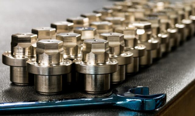
Precision engineered components and the standards behind reliable manufacturing
What precision engineered components means in practice
Precision engineered components are not simply small parts, and they are not defined only by tight tolerances. In manufacturing, the term is most useful for components whose performance depends on controlled geometry, material condition, surface integrity and documented verification. A shaft, valve body, motion-control housing, sealing seat, connector or fixture element may qualify when failure would affect fit, motion, leak-tightness, fatigue life or assembly yield. For buyers comparing suppliers, designs or processes, the key question is not whether a process can hold an impressive tolerance once. It is whether the requirement is functional, measurable, repeatable and backed by evidence across production. More background on related topics is available in the precision components category.
Public manufacturing references from ISO, ASME, NIST, SAE, IAQG and AIAG point to the same practical lesson: precision is a chain. It starts with a clear product definition, continues through process planning and ends with inspection records that engineering, quality and purchasing teams can understand and use.
Why tolerance alone does not define precision
A drawing can specify a very small numerical tolerance and still fail to produce a usable component if that tolerance is not tied to function. Conversely, a component with moderate dimensional limits may be highly engineered when the datum structure, surface requirement, material state and inspection method all match how the part works in an assembly.
This is why geometric dimensioning and tolerancing matters. ASME Y14.5 is widely treated as an authoritative reference for communicating dimensioning and tolerancing requirements in engineering drawings. Its value is not that it makes every feature tighter. Its value is that it helps designers state which features control location, orientation, form and relationships to datums. Without that shared language, a machinist, inspector and design engineer may measure the same part in different ways and reach different conclusions.
| Specification area | What it controls | Risk if it is unclear |
|---|---|---|
| Datum scheme | How the part is located for manufacturing and inspection | Good parts may be rejected or bad parts may pass because measurement setups differ |
| Geometric tolerance | Form, orientation, position or runout relative to function | Features may meet plus-minus dimensions but fail in assembly |
| Surface finish | Friction, sealing, wear, coating adhesion and fatigue behavior | The component may fit but perform poorly under load or motion |
| Material and heat treatment | Strength, hardness, corrosion behavior and stability | Dimensions may be correct before the part distorts, wears or fails in service |
| Inspection method | How conformity is proven | Measurement uncertainty may hide process variation or create disputes |
The practical conclusion is straightforward: precision should be specified around function. Tightening every dimension increases cost and can reduce manufacturability, while leaving critical relationships undefined creates downstream risk.
The engineering controls behind reliable precision
Clear product definition
A precision component begins with a drawing, model or technical data package that communicates design intent. That package should identify critical-to-quality features, required standards, material grade, finish, coatings, special processes and acceptance criteria. If a model-based definition is used, the same discipline still applies: the digital model must make requirements inspectable, not merely visible.
For edition-controlled standards, purchasing and engineering documents should state the exact standard and revision when it matters. A vague note such as “standard tolerance applies” may be acceptable for noncritical work, but it is weak for precision engineered components that must move between design teams, production sites and inspectors.
Process capability instead of one-time success
Precision manufacturing is repeat production under controlled variation. CNC milling, turning, grinding, EDM, stamping, forming and additive manufacturing can all produce high-value components, but each process has its own sources of variation. Tool wear, thermal expansion, fixture repeatability, machine condition, coolant control, powder or bar-stock variation and operator setup decisions can all influence the result.
The strongest manufacturing plans connect feature requirements to a process capability plan. That may include controlled tooling, in-process checks, offset rules, environmental control, statistical process control for key dimensions or documented approval before a process change. The purpose is not paperwork for its own sake. It is to prevent a stable first article from becoming unstable in production.
Measurement traceability and uncertainty
NIST describes metrological traceability as an unbroken chain of calibrations to specified reference standards, often national or international standards. In practical terms, an inspection report is only as useful as the measurement system behind it. Calipers, micrometers, gauges, CMMs, optical systems and surface instruments need suitable resolution, current calibration status, setup instructions and operators who understand the feature being measured.
Precision work also requires attention to measurement uncertainty. A measuring device with impressive resolution does not automatically prove that a component conforms. Temperature, fixturing, probe strategy, part cleanliness and human handling can all influence results. NIST guidance on measurement variability has long emphasized that day-to-day measurement variation can exceed the apparent precision of an instrument when conditions are not controlled.
How manufacturing routes shape the specification
No manufacturing process should be selected only because it is labeled “precision.” The better question is which process can meet the functional requirement with stable cost, quality and lead time. The same component may need rough machining, heat treatment, finish grinding, coating and final inspection before it is fit for use.
| Manufacturing route | Where it fits precision components | Specification points to watch |
|---|---|---|
| CNC milling and turning | Housings, brackets, shafts, manifolds and complex metal parts | Datum setup, tool access, burr control, material stress relief and inspection access |
| Swiss turning | Small cylindrical parts, pins, connectors and medical-style micro components | Long slender geometry, concentricity, material feed variation and surface finish |
| Grinding and honing | Bearing surfaces, sealing diameters, bores and high-finish features | Thermal damage, roundness, cylindricity, surface texture and cleaning |
| EDM | Hard materials, fine slots, internal features and toolmaking details | Recast layer, surface integrity, electrode wear and post-process finishing |
| Stamping and forming | Thin metal contacts, springs, clips and repeatable sheet-metal features | Tool wear, springback, burr direction, grain direction and progressive-die control |
| Casting, forging and near-net shapes | Structural or fluid-handling parts where material efficiency matters | Machining stock, porosity limits, heat treatment and critical machined interfaces |
| Additive and hybrid manufacturing | Lightweight, internal-channel or low-volume complex geometry | Material qualification, build orientation, surface finishing, porosity and final machining |
NIST’s additive manufacturing measurement programs highlight why newer routes need strong qualification. Additive processes can shorten the path from design to part, but they also introduce challenges in material characterization, in-process monitoring, process qualification and final verification. For precision components, additive manufacturing is often most useful when combined with machining, heat treatment and inspection rather than treated as a standalone shortcut.
Quality evidence buyers should request
Precision manufacturing is easier to evaluate when quality evidence is defined before production begins. The necessary evidence depends on industry, risk and part function. A prototype bracket may need only a dimensional report and material certificate. A safety-related aerospace or automotive component may need formal approval documentation, controlled change records and retained samples.
ISO 9001 defines requirements for a quality management system and is used broadly across industries. It does not prescribe the exact way a machine shop must make a component, and certification alone does not prove that a specific part conforms. It does, however, provide a framework for controlled processes, documented information, competence, performance evaluation and continual improvement. See also: buying guides.
Sector-specific systems may add more detail. AIAG’s Production Part Approval Process is associated with automotive part approval activities, forms, records and sample retention. SAE AS9102 establishes documentation requirements for first article inspection in aerospace. ISO 13485 applies quality management requirements specific to medical devices. These references are not interchangeable; the buyer, drawing or contract should identify which evidence is required.
- First article inspection report: confirms that the first representative part or production setup meets drawing and specification requirements.
- Material certificate: supports traceability for alloy, grade, chemistry, mechanical properties or heat treatment condition when applicable.
- Dimensional inspection report: records measured values for defined characteristics, ideally tied to drawing balloons or model characteristics.
- Control plan: explains how key features will be monitored during production rather than checked only at the end.
- Gauge and calibration records: show that measurement devices are suitable and traceable for the required inspection.
- Nonconformance and change records: document how deviations, rework, substitutions or process changes are reviewed and approved.
A useful purchasing rule is to request evidence that reduces a specific risk. Asking for every possible document can slow sourcing and create confusion. Asking for the right documents helps both the buyer and the manufacturer focus on features that matter.
Design and sourcing decisions that reduce manufacturing risk
Many precision problems are designed into a component before a supplier ever sees it. Features that are difficult to fixture, inspect or machine consistently may add cost without improving performance. Early manufacturability review is therefore one of the most practical ways to improve precision outcomes.
Design teams should identify which requirements are functional and which are legacy preferences. If a tolerance was copied from an older drawing, it should be reviewed against the current assembly need. If a surface finish is specified on a non-contact area, it may add avoidable cost. If a datum does not match how the part is used, inspection may not predict real assembly performance.
Sourcing teams should also avoid treating all “precision” suppliers as equivalent. A supplier that excels at miniature turned parts may not be the right choice for large ground plates. A shop experienced in prototype machining may not have the controls needed for high-volume automotive approval. A facility with advanced inspection equipment may still need clear drawings and stable process planning to produce consistent results.
The most productive supplier discussions usually cover five points: the function of the component, the features that carry risk, the proposed manufacturing sequence, the inspection plan and the evidence needed for acceptance. This keeps the conversation technical rather than promotional.
Frequently asked questions
Are precision engineered components always more expensive?
Not always. They may cost more when they require tighter process control, special materials, finishing or inspection. However, a well-engineered specification can reduce total cost by removing unnecessary tolerances, preventing assembly failures and lowering rework.
What is the difference between precision parts and precision engineered components?
“Precision parts” often describes a finished item with tight or repeatable dimensions. “Precision engineered components” is broader because it includes the engineering logic behind the part: function, datum strategy, material condition, process control, inspection and documentation.
Which standard is most important for precision components?
There is no single universal standard for every component. ASME Y14.5 is important for dimensioning and tolerancing, ISO 9001 is widely used for quality management systems, and sector standards such as AS9102, IATF 16949-related requirements, PPAP or ISO 13485 may apply depending on the market and contract.
How can a buyer know whether a component is truly precise?
The buyer should compare the drawing or model requirements with inspection evidence, material records, process controls and supplier change discipline. A part is not truly precise because it looks complex; it is precise when its critical characteristics are defined, produced and verified in a repeatable way.
Should every dimension be made as tight as possible?
No. Over-tightening noncritical dimensions can increase cost, extend lead time and make production less stable. Precision engineering means applying tight control where function requires it and allowing practical manufacturing variation where it does not affect performance.