Lathe tools explained for turning, facing, grooving and threading
What lathe tools do in turning work
Lathe tools shape a rotating workpiece by removing material along a controlled path. In most turning jobs, the question is not just which tool can cut metal. The better question is which tool geometry, holder style, cutting material and setup will produce the required diameter, face, groove, thread or bore without chatter, poor chip control or early tool wear.
Selection should start with the operation, then move to the workpiece material, machine rigidity, coolant availability, tolerance and surface finish target. Standards such as ISO 1832:2017 for indexable insert designations and ISO 513:2012 for cutting material application groups help shops compare tooling more consistently, but they do not replace process judgment at the machine.
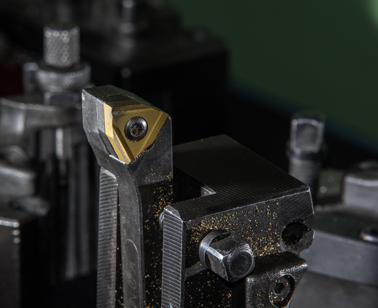
In daily shop use, the term lathe tools may refer to hand-ground high-speed steel tools, brazed carbide tools, indexable turning inserts, boring bars, parting blades, grooving tools, threading tools, knurling tools and center drills used on a lathe. On CNC turning centers, it often means modular holders and indexable inserts mounted in a turret. On manual engine lathes, it may include tool bits held in a quick-change post. The cutting principles remain similar: edge position, chip flow, workholding rigidity and cutting conditions determine whether the tool performs predictably.
For more context on machining equipment and manufacturing topics, visit our machine tools category.
Main types of lathe tools and where they fit
Choosing a lathe tool starts with the feature being machined. A tool that works well along an outside diameter may be a poor choice for a narrow groove or an internal bore. The table below summarizes common tool families and the main selection points.
| Tool type | Typical use | Selection notes | Common limitation |
|---|---|---|---|
| External turning tool | Roughing and finishing outside diameters | Match insert shape, nose radius and chipbreaker to depth of cut and feed | Can chatter if overhang, workholding or edge geometry is not suitable |
| Facing tool | Machining flat end faces and shoulders | Requires clearance near the centerline and stable chip evacuation | Surface finish may change near the center as cutting speed drops |
| Boring bar | Internal turning, enlarging holes and improving bore accuracy | Short, rigid bars are preferred; carbide bars can improve stiffness in deeper bores | Long overhang increases vibration risk |
| Grooving and parting tool | Cutting grooves, undercuts and separating parts | Blade width, insert support and chip narrowing geometry matter | Highly sensitive to alignment and deflection |
| Threading tool | External and internal threads | Profile, pitch, insert orientation and infeed method must match the thread form | Small geometry errors can create rejected threads |
| Form tool | Cutting a specific radius, contour or special profile | Useful for repeat features when the machine and workpiece are rigid enough | Large contact area raises cutting forces |
| Knurling tool | Producing grip patterns by forming or cutting | Wheel pitch, pressure, diameter relationship and alignment affect pattern quality | Form knurling can load the spindle and workholding heavily |
This classification is more practical than grouping tools only by material. A carbide turning insert may be a strong choice for steel OD roughing but unsuitable for a fine internal thread. A simple HSS tool bit may run slower than coated carbide, yet still be useful for one-off work, interrupted setups or special profiles that are easy to grind in-house.
How insert geometry changes the cut
Modern lathe tools often use indexable inserts because they provide repeatable cutting edges and standardized shapes. An insert, however, is not just a generic triangle or diamond. Shape, clearance, tolerance, chipbreaker, rake, edge preparation, nose radius and grade all influence cutting pressure, chip formation, accuracy and finish.
Insert shape and approach angle
Insert shape affects both edge strength and accessibility. Round and square inserts can provide strong cutting edges for roughing, while 80-degree diamond shapes are common general-purpose choices. More pointed shapes, such as 55-degree and 35-degree diamonds, can reach tighter profiles and shoulders, but they usually sacrifice some edge strength.
The toolholder also determines the approach angle, sometimes called the entering or lead angle. Changing this angle changes chip thickness, radial cutting force and the direction in which the tool loads the workpiece. Manufacturer turning guides from companies such as Sandvik Coromant, Seco Tools and Kennametal commonly treat insert shape and lead angle as linked decisions. The same insert may behave differently in different holders because the holder changes how the edge meets the workpiece.
Nose radius and surface finish
The nose radius is one of the most visible geometry choices. A larger radius generally strengthens the corner and can improve theoretical surface finish at the same feed. It can also increase radial force, which may make chatter more likely on slender workpieces or less rigid machines. A smaller radius reduces cutting pressure and helps with fine details, but it is less tolerant of heavy feed and interrupted cuts.
A common geometric estimate for turned surface roughness is that ideal Ra is approximately feed squared divided by 32 times the nose radius, when feed and radius are in the same units. This is useful for comparison, not as a guaranteed shop result. Built-up edge, machine vibration, material tearing, insert wear and coolant conditions can all make the actual finish worse than the calculated value.
Chipbreaker and rake
Chipbreakers are designed to curl, narrow or break chips within a defined range of feed and depth of cut. If the feed is too light, the chip may not form as intended. If the depth of cut is too heavy, chip packing, high tool load or edge failure can occur. Positive rake geometries cut more freely and are useful on lower-power machines, internal boring bars and gummy materials. Stronger negative geometries are often selected for stable roughing and harder conditions, but they require more machine rigidity.
Tool material and grade selection
Lathe tool material should match the workpiece material, production volume, machine capability and cost target. The best choice is not always the hardest tool material. Toughness, heat resistance, edge sharpness and fracture resistance all matter.
High-speed steel and brazed carbide
High-speed steel remains useful for manual lathes, prototype work, plastics, aluminum, soft metals and special forms. It can be sharpened easily and ground to custom angles, which makes it flexible when geometry matters more than cycle time. Its main limitations are heat resistance and wear life at higher cutting speeds.
Brazed carbide tools use a carbide tip permanently joined to a steel shank. They can be economical and rigid, especially for simple manual turning, but resharpening requires grinding equipment and skill. Because the cutting geometry is not changed as quickly as an indexable insert, brazed tools are less convenient where materials and jobs change frequently.
Indexable carbide inserts
Indexable carbide is the standard choice in many production turning operations. Inserts are available in different grades, coatings and chipbreaker geometries. ISO-style designations help identify insert shape, clearance, tolerance, clamping style, size, thickness and corner radius, although manufacturers may add proprietary suffixes for chipbreakers, coatings or wiper geometries.
For practical selection, start with the workpiece material group, then narrow the choice by operation. Steel, stainless steel, cast iron, non-ferrous metals, heat-resistant alloys and hardened materials place different demands on the cutting edge. A sharp grade that works well in aluminum may fail quickly in abrasive cast iron. A tough roughing grade may survive interrupted steel cuts but leave a poorer finish than a finishing geometry. See also: buying guides.
Ceramic, CBN and PCD tools
Advanced cutting materials are valuable within specific operating windows. Ceramics can support high-speed machining of some cast irons and heat-resistant alloys, but they are brittle and need suitable conditions. Cubic boron nitride is associated with hard turning and abrasive ferrous materials. Polycrystalline diamond can be highly effective on non-ferrous metals and abrasive composites, but it is generally not selected for conventional steel turning because of chemical wear mechanisms at high temperature. These tools should be chosen from current manufacturer data for the exact material and operation.
Setup factors that decide whether the tool performs
A well-selected tool can still fail if the setup is weak. On a lathe, rigidity is a complete system: spindle, chuck or collet, workpiece stick-out, tailstock support, turret or toolpost, holder, insert seating and cutting parameters all interact.
- Center height: Turning tools should be set accurately on center. A tool above or below center changes rake and clearance behavior and can cause poor finish, rubbing or dimensional error.
- Overhang: Keep turning holders and boring bars as short as practical. Internal boring is especially sensitive because bar deflection increases rapidly as the length-to-diameter ratio rises.
- Insert seating: Chips, dents or worn seats under an indexable insert can prevent repeatable positioning and may crack the insert under load.
- Workholding: Thin-wall parts, long shafts and interrupted shapes may need tailstock support, steady rests, softer geometry or reduced cutting forces.
- Coolant and chip evacuation: Coolant can reduce heat and improve chip evacuation in many operations, but some tool materials or interrupted cuts may require dry or carefully controlled conditions. Follow the toolmaker’s data for the insert grade.
Speeds and feeds should come from the tool manufacturer’s recommendations for the grade, geometry and material, then be adjusted after observing chips, sound, finish and wear. The goal is not to run the highest possible speed. It is to keep the cut stable, predictable and economical.
Safety and maintenance checks before cutting
Lathe work involves rotating parts, sharp chips, possible workpiece ejection and hot cutting zones. OSHA machine-guarding materials for U.S. general industry identify hazards such as points of operation, rotating parts, flying chips and sparks. Safety requirements vary by jurisdiction and machine type, so operators and employers should follow current regulations, the machine manual and site procedures.
Before starting a cut, confirm that the chuck key is removed, jaws and fixtures are secure, guarding or shields are in place, the toolpath clears the chuck and shoulder, and the tool is clamped correctly. Loose clothing, jewelry and gloves that can catch on rotating equipment are serious hazards. Chip hooks, pliers or approved tools should be used to handle stringy or hot chips; hands should not be used to clear chips near a rotating spindle.
Maintenance matters as well. Dull inserts raise heat and force. Damaged toolholders lose repeatability. Built-up chips under clamps can tilt an insert. A basic inspection routine often prevents problems that might otherwise be blamed on the insert grade.
A practical workflow for choosing lathe tools
A structured workflow helps avoid random trial and error. The following sequence works for both manual and CNC turning decisions.
- Define the feature: OD turning, facing, boring, grooving, parting, threading, profiling or knurling.
- Identify the workpiece material: Include alloy, hardness, condition and whether the cut is continuous or interrupted.
- Check machine and setup rigidity: Consider horsepower, spindle condition, workpiece stick-out, holder overhang and toolpost or turret stability.
- Select holder style: Choose the approach angle, handedness, clearance and reach needed for the feature.
- Select insert geometry: Match shape, nose radius, chipbreaker and rake to depth of cut, feed and finish target.
- Select grade and coating: Use manufacturer data for the material group and cutting condition.
- Run a controlled first cut: Observe chip shape, sound, spindle load, finish and dimensional stability before increasing material removal rate.
For troubleshooting, connect symptoms to likely causes rather than changing several variables at once.
| Symptom | Likely checks | Possible correction |
|---|---|---|
| Chatter marks | Overhang, workholding, nose radius, feed, cutting speed | Shorten setup, reduce radial force, change speed, use a sharper or smaller-radius geometry |
| Stringy chips | Chipbreaker range, feed, depth of cut, material ductility | Move into the chipbreaker’s working range or change geometry |
| Poor finish | Edge wear, built-up edge, vibration, feed and nose radius relationship | Replace edge, adjust speed/feed, improve rigidity or select finishing geometry |
| Insert chipping | Interrupted cut, grade toughness, edge preparation, clamping | Use tougher grade, stronger geometry, better support or less aggressive entry |
| Taper or size drift | Tool deflection, thermal growth, tailstock alignment, wear | Improve support, compensate carefully and verify alignment |
Frequently asked questions
What are the most common lathe tools for beginners?
For basic manual lathe work, the most common tools are an external turning tool, facing tool, boring bar, parting tool, threading tool and center drill. Many beginners start with HSS or general-purpose carbide inserts because they are easier to understand before moving into specialized chipbreakers and grades.
Are carbide lathe tools always better than HSS?
No. Carbide usually supports higher cutting speeds and longer production runs, but HSS can be better for custom shapes, low-speed machines, delicate work, interrupted learning setups and quick sharpening. The better choice depends on the machine, material, geometry and economics of the job.
How do I choose the nose radius for a turning insert?
Use the required finish, feed rate, depth of cut and setup rigidity as the main guides. Larger radii can improve theoretical finish and edge strength, but they increase radial force. Smaller radii reduce cutting pressure and improve access, but they are less robust under heavy feeds.
Why does a lathe tool chatter even when the insert is new?
Chatter is often a system problem rather than only an insert problem. Common causes include excessive tool overhang, a long unsupported workpiece, weak clamping, a large nose radius, unsuitable cutting speed, thin-wall workpieces or a boring bar that is too slender for the depth.
Can one lathe tool handle turning, facing and profiling?
Some general-purpose turning holders can perform several operations, especially on simple parts. However, grooving, parting, threading, deep boring and close shoulder work usually require dedicated tools. Using the right tool for the feature improves accuracy, chip control and edge life.