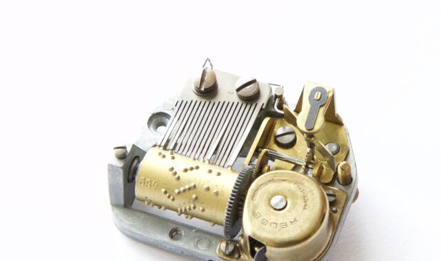
Precision miniature components in modern manufacturing and quality control

What makes precision miniature components different
Precision miniature components are small mechanical parts where size, feature density, tolerance stack-up, surface condition, and inspection method all have to be managed together. A part is not precision simply because it is small. It becomes a precision component when its dimensions, geometry, material behavior, and repeatability must be controlled closely enough to support a larger assembly, device, or motion system. In miniature work, a small burr, a slightly oversized radius, or an internal feature that is hard to measure can affect fit, movement, sealing, conductivity, or fatigue life.
The challenge is therefore not just making tiny parts. It is aligning design intent, process capability, tooling access, metrology, and documentation before production starts. For more related manufacturing topics, see the precision components section.
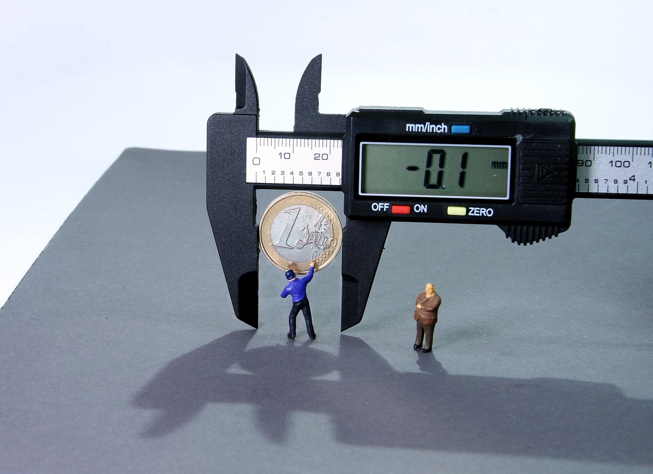
Typical applications include medical device subassemblies, electrical connectors, micro motion systems, optical hardware, miniature fasteners, sensor housings, aerospace mechanisms, watch components, and compact automation equipment. These fields have different regulatory and performance requirements, but they share the same practical issue: as component size decreases, the allowable margin for process variation becomes smaller.
Key design factors that affect manufacturability
Miniature components often run into production problems when the design is dimensionally complete but not process-aware. A drawing may define every feature, yet still leave open questions: Can a tool reach the pocket? Can a drill hold position in a deep micro hole? Can the edge be deburred without changing a critical dimension?
Feature size, aspect ratio, and tool access
Small holes, thin walls, narrow slots, and sharp internal corners should be reviewed early. The smaller the cutter or electrode, the more sensitive the process becomes to tool deflection, vibration, heat, and wear. A deep, narrow feature may be possible, but it may require slower machining, special tools, staged operations, or an alternative process such as electrical discharge machining, laser processing, stamping, or micro molding, depending on material and volume.
Designers can reduce risk by identifying which features are functionally critical and which are clearance, cosmetic, or non-critical. This helps manufacturing teams focus effort where it affects assembly performance, rather than applying the same level of control to every dimension on the drawing.
Tolerance stack-up in compact assemblies
Miniature assemblies may contain shafts, pins, springs, spacers, housings, and electrical contacts in very limited space. Even when each component meets its individual tolerance, the combined stack-up can create binding, looseness, electrical misalignment, or sealing variation. Geometric dimensioning and tolerancing frameworks, such as ASME Y14.5 or ISO GPS standards, are often used to define datums, orientation, position, and runout more clearly than plus-minus dimensions alone.
The practical goal is to control the relationships that matter to function. For example, the position of a pin hole relative to a locating datum may be more important than the absolute outside size of a bracket. In the same way, flatness or perpendicularity may matter more than nominal thickness if the part must seat against another precision surface.
Material behavior at small scale
Material selection can change the entire manufacturing route. Stainless steels may provide corrosion resistance and strength but can work-harden during machining. Titanium alloys may be attractive for medical and aerospace uses, while also being difficult to machine and deburr. Copper alloys offer conductivity but may smear during cutting. Engineering plastics can reduce weight and electrical conductivity, yet may move with moisture, temperature, or residual stress.
At miniature scale, heat input, clamping pressure, and cutting force can distort thin sections. A material that performs well in a larger part may need a different toolpath, support method, or inspection plan when the same geometry is miniaturized.
Manufacturing processes used for miniature precision parts
No single process is best for all precision miniature components. The right choice depends on geometry, material, tolerance, surface finish, volume, lead time, and downstream assembly needs. In many projects, the most reliable route combines several processes instead of relying on one machining or forming operation.
| Process | Where it fits | Main limitation to review |
|---|---|---|
| Micro CNC milling and turning | Small metal or plastic parts with controlled external and internal features | Tool access, tool wear, burr control, and workholding stability |
| Swiss-type machining | Long, slender, high-volume turned parts such as pins, shafts, bushings, and miniature fasteners | Best suited to rotational or bar-fed geometries |
| Wire or sinker EDM | Hard metals, fine profiles, slots, and features that are difficult to cut conventionally | Material must be electrically conductive; recast layer and surface requirements may need review |
| Laser cutting or laser micromachining | Thin materials, fine patterns, and small openings | Heat-affected zones, taper, edge quality, and material reflectivity |
| Micro stamping or forming | Repeatable thin metal parts at higher volumes | Tooling investment, springback, burr direction, and material strip control |
| Micro injection molding | Small polymer components with repeatable geometry at volume | Mold flow, shrinkage, gate design, and inspection of fine features |
The table shows why process selection should happen before tolerances are finalized. A tolerance that is routine in one feature orientation may be costly or unstable in another. Likewise, a surface requirement that appears minor on a drawing may require secondary finishing if the selected process leaves tool marks, recast material, or a burr direction that interferes with assembly.
Inspection and measurement challenges
For miniature parts, measurement can be as demanding as manufacturing. A component may have features too small for conventional contact gauges, surfaces too delicate for high probing force, or internal geometries that cannot be reached without sectioning. The inspection plan should therefore be developed alongside the manufacturing plan, not added after parts are made.
Choosing the right measurement method
Contact coordinate measuring machines can be useful for accessible features, but probe size and contact force must be compatible with the part. Optical measurement, vision systems, confocal methods, laser scanning, and computed tomography may be considered when features are very small, fragile, or hidden. Each method has limits. Optical methods depend on lighting, contrast, edge detection, and surface reflectivity. CT can reveal internal geometry, but it requires careful validation for resolution, material density, and measurement uncertainty.
Good inspection practice defines the measurement method, fixture, datum setup, sampling plan, and acceptance criteria. If a drawing specifies a dimension but the inspection team cannot measure it reliably, the requirement is incomplete from a production-control point of view.
Measurement uncertainty and false confidence
Precision inspection should not only report a measured value. It should also account for measurement uncertainty, repeatability, and the risk of accepting or rejecting parts near a tolerance limit. This becomes especially important when tolerance bands are narrow. A measurement system that is adequate for larger components may not be capable enough for miniature features.
Production teams commonly review gauge repeatability and reproducibility, calibration status, fixture stability, operator influence, and environmental conditions. Temperature, vibration, dust, part cleanliness, and even static charge can become more noticeable as part size and tolerance range decrease.
Surface finish, burrs, and edge quality
Small parts can look acceptable under low magnification while still containing burrs or surface defects that create functional problems. A burr that would be insignificant on a large bracket may block a micro slot, change electrical contact, contaminate a medical device pathway, or prevent a miniature mechanism from moving freely. See also: buying guides.
Edge quality should be specified in functional language whenever possible. Instead of relying only on a generic deburr note, the drawing or quality plan should define whether edges must be broken, remain sharp, avoid loose particles, maintain a sealing land, or protect a mating surface. The correct requirement depends on function. A cutting edge, spring contact, and fluidic channel cannot use the same edge condition by default.
Finishing options may include tumbling, brushing, abrasive flow, electropolishing, chemical deburring, thermal deburring, ultrasonic cleaning, or manual work under magnification. Each option can solve one problem while creating another. Aggressive finishing may round edges, alter dimensions, change surface texture, or trap media in small holes. This is why trial validation is often necessary before a finishing method is released for repeat production.
Quality documentation and risk control
Precision miniature components benefit from clear documentation because many defects are not obvious without magnification, specialized gauges, or functional testing. Drawings, control plans, inspection reports, material certificates, process parameters, and nonconformance records help connect design requirements to repeatable production.
Depending on the industry, quality systems and standards may influence documentation. Medical manufacturing may involve ISO 13485 requirements. Aerospace work may use AS9100-based quality systems. General industrial projects may rely on ISO 9001 frameworks, customer-specific inspection plans, and agreed acceptance criteria. The important point is not the label alone, but whether the documentation controls the actual risks of the part.
A practical risk checklist
- Critical features: Identify the dimensions and geometric controls that directly affect fit, motion, sealing, electrical contact, or safety.
- Process capability: Confirm whether the chosen manufacturing method can hold the required tolerance repeatedly, not only on a prototype.
- Workholding: Review how the part will be supported without distortion, marking, or loss of datum accuracy.
- Burr strategy: Define acceptable and unacceptable edge conditions before production, especially near holes, slots, and mating faces.
- Inspection access: Verify that critical features can be measured with a capable method and fixture.
- Cleanliness: Consider whether particles, oil, abrasive residue, or trapped media could affect function or downstream assembly.
- Packaging: Protect small parts from mix-ups, deformation, corrosion, electrostatic damage, and handling loss.
This checklist is not a substitute for a formal quality plan, but it highlights where miniature precision work commonly creates hidden risk. The earlier these points are reviewed, the less likely the project is to depend on late-stage sorting or rework.
Cost drivers and sourcing considerations
The cost of miniature components is not determined only by material weight. In many cases, raw material is a minor part of total cost. Larger cost drivers include engineering review, tooling, machine time, tool wear, inspection time, finishing, cleaning, yield loss, packaging, and documentation. A very small part can be expensive if it requires slow machining, fragile handling, or 100% inspection under magnification.
Buyers and engineers can make sourcing more efficient by sharing the real function of the part, expected annual volume, material requirements, drawing revision history, inspection expectations, and any known failure modes. When suppliers understand which features are critical, they can suggest process routes or tolerance changes that reduce cost without weakening performance.
It is also useful to separate prototype intent from production intent. A prototype may be machined from a solid block to validate geometry, while production may require stamping, molding, Swiss machining, or a hybrid route. If the prototype process is treated as the final process without review, the project may carry unnecessary cost into production.
Frequently asked questions
Are precision miniature components always more expensive than larger parts?
Not always. Size alone does not determine cost. A miniature part becomes expensive when it requires tight tolerances, hard-to-reach features, special materials, difficult deburring, validated cleaning, high inspection coverage, or low-volume setup. A simple small stamped part may be economical at volume, while a complex micro-machined part may remain costly.
What tolerances are realistic for miniature components?
Realistic tolerances depend on material, feature geometry, process, datum scheme, inspection method, and production volume. It is better to ask which tolerances are functionally necessary than to apply the tightest possible values across the whole drawing. Overly tight non-critical tolerances increase cost and can make inspection more difficult without improving performance.
How should burrs be specified on small parts?
Burr requirements should be tied to function. The drawing or quality plan should describe where burrs are not allowed, which edges may be broken, whether particles are unacceptable, and whether a sharp functional edge must be preserved. A generic deburring note may not be enough for miniature holes, slots, contacts, and sealing surfaces.
When should inspection planning begin?
Inspection planning should begin during design review. If a critical feature cannot be measured reliably, the design, datum structure, tolerance method, or process route may need adjustment. Early measurement planning helps prevent disputes after parts are produced.
Conclusion
Precision miniature components require a disciplined connection between design, manufacturing, inspection, finishing, and documentation. Successful projects do not treat miniaturization as a simple scaling exercise. They identify functional features, choose a process that can hold them, define measurable acceptance criteria, and control surface and edge conditions that may be invisible at first glance.
For engineers, buyers, and manufacturing teams, the central lesson is practical: the smaller the component, the more important the handoff becomes. A clear drawing, realistic tolerance strategy, capable process, and validated inspection plan can reduce rework and make miniature parts more reliable in the assemblies where they matter most.