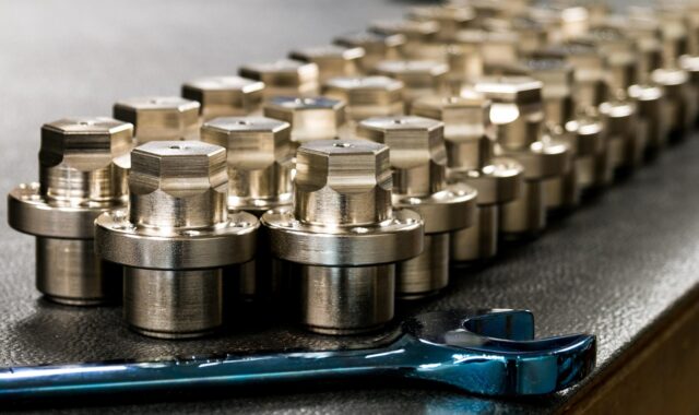
How precision mechanical components are specified, manufactured, and verified
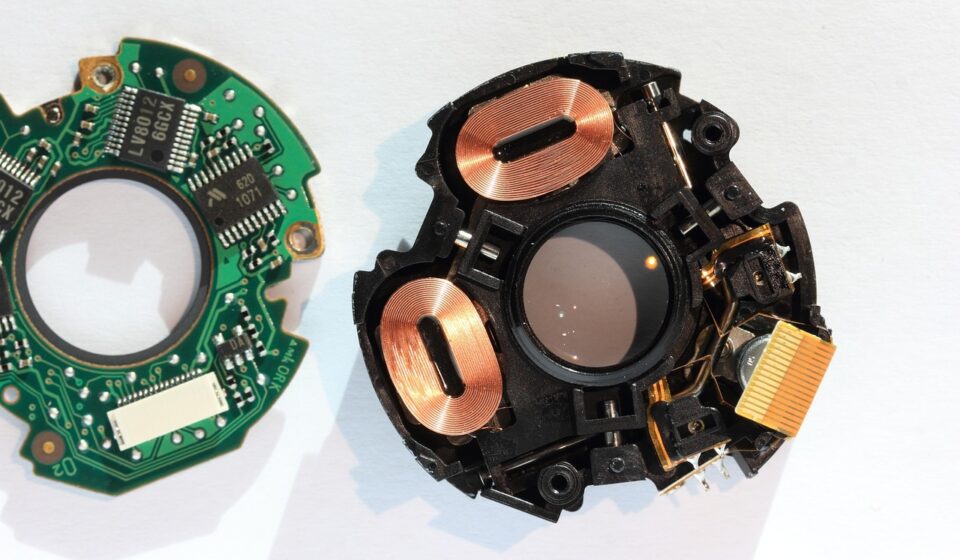
What makes precision mechanical components different?
Precision mechanical components are parts whose performance depends on controlled dimensions, geometry, material condition, surface quality, and repeatable inspection. Tight tolerances alone do not make a part precise. A component becomes precise when its critical features are specified around function, manufactured through a stable process, and verified with measurement methods appropriate for the tolerance. For engineers, buyers, and manufacturing teams, the practical question is whether the drawing, process plan, and inspection record all describe the same functional requirement.
That is why precision work usually sits at the intersection of design engineering, machining, metrology, materials, and quality documentation. A shaft, valve body, optical mount, bearing seat, robot joint part, or medical device component may all be called precision parts, but each one needs a different balance of size tolerance, geometric control, finish, cleanliness, and traceability.
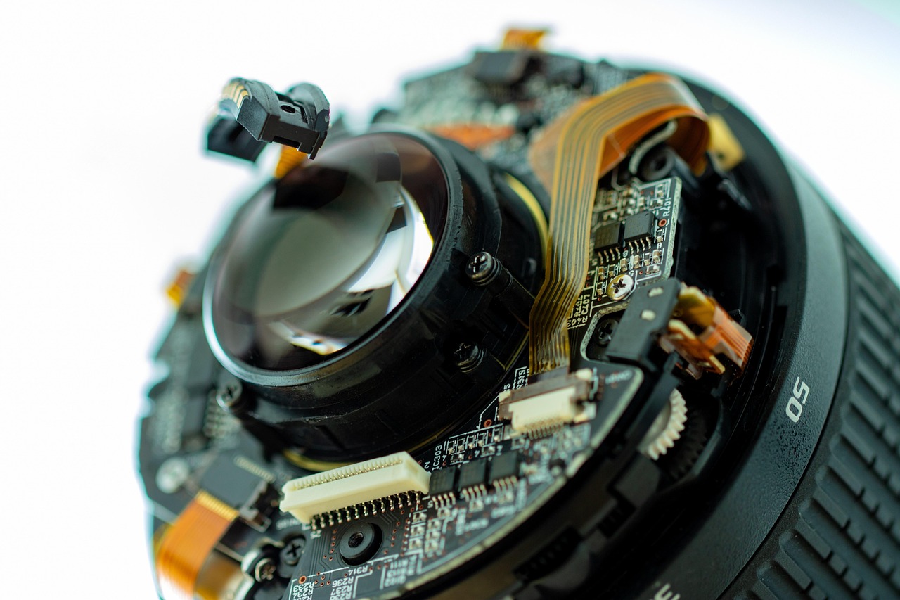
Specification starts with function, not with the smallest tolerance
The most useful specifications start by identifying how the part will be used. A locating bore may need positional accuracy relative to a datum surface. A sealing face may need flatness and surface finish. A sliding part may need clearance, hardness, and a controlled burr condition. A cosmetic, non-functional edge may need only a general tolerance. Treating all of these features equally often adds cost without improving performance.
Geometric dimensioning and tolerancing is widely used because it connects the drawing to part function. ISO 1101:2017 defines a symbol language for geometrical specification and interpretation of workpieces, while ASME Y14.5-2018 is a major GD&T reference used for dimensioning and tolerancing in many engineering environments. ISO 286 is also used for tolerance classes and limits for linear sizes, especially where hole and shaft fits are important. (committee.iso.org)
| Functional need | Typical specification focus | Why it matters |
|---|---|---|
| Rotating or sliding fit | Diameter tolerance, roundness, surface finish, hardness | Controls clearance, friction, wear, and assembly consistency |
| Mounting or locating feature | Datum structure, position tolerance, perpendicularity, flatness | Helps the part assemble correctly with mating components |
| Sealing surface | Flatness, roughness, waviness, material compatibility | Reduces leakage risk and uneven compression |
| High-load feature | Material grade, heat treatment, fillet radius, surface integrity | Supports fatigue strength and dimensional stability |
| Appearance or handling edge | Deburr requirement, chamfer, coating condition | Improves safety, handling, and downstream assembly |
A precise specification is selective. It tightens the features that carry function and relaxes the features that do not. This gives manufacturers enough control to make the part reliable while avoiding unnecessary cycle time, scrap, special tooling, and inspection burden.
Key design inputs that affect manufacturability
Datum selection and feature relationships
Datum selection is one of the most important decisions in a precision component drawing. Datums should represent how the part is assembled, located, or used in service. If the datum scheme reflects only a convenient modeling surface, inspection may pass a part that does not assemble well, or reject a part that would function correctly.
For example, a bracket with two precision bores should usually be controlled from the surfaces and features that define its assembly position. A turned shaft may need concentricity, runout, or circular runout controls based on its bearing seats and rotating surfaces. The right datum structure reduces ambiguity between design intent, machining setup, and inspection setup.
Tolerance stack-up and assembly risk
Precision mechanical components rarely work alone. They operate as part of an assembly where several tolerances combine. A single component may meet its own print, but the assembly can still fail if the stack-up was not considered. This is common in compact mechanisms, actuators, gear housings, fluid systems, and instruments where multiple machined parts interact.
Good tolerance planning identifies the features that drive assembly variation. It also distinguishes between interchangeable mass production requirements and matched or adjusted assemblies. Interchangeability usually requires more disciplined tolerancing and process capability, while adjusted assemblies may allow controlled fitting but require stronger work instructions and documentation.
Surface texture and edge condition
Surface requirements should be specified only where they affect performance. A low roughness value may be necessary for sealing, fatigue resistance, precision sliding, or optical alignment. On other surfaces, it may only add cost. Edge condition is just as important. Burrs can interfere with assembly, contaminate systems, damage seals, or create safety hazards, especially in small components with intersecting holes or fine features.
Because deburring can change dimensions and edge geometry, it should not be treated as an afterthought. Drawings and work instructions should clarify whether edges require a simple break, a controlled chamfer, no sharp burrs, or a defined radius.
Manufacturing routes for precision parts
Precision mechanical components can be produced through several manufacturing routes. CNC turning and milling are common for complex metal parts. Grinding, honing, lapping, and polishing may be added when geometry, size, or surface finish requirements exceed what a primary cutting process can hold economically. EDM may be useful for hard materials, small internal features, sharp profiles, or low-force cutting conditions. The right process depends on geometry, material, tolerance, volume, finish, and inspection requirements.
Stable precision manufacturing depends on more than machine accuracy. Workholding must locate the part repeatably without distortion. Cutting tools must be monitored for wear. Coolant, chip control, and thermal behavior must be managed. Parts may need stress relief or intermediate inspection between operations. If a feature is finished before a heavy roughing operation, later stress movement can compromise accuracy.
Process sequence is especially important for thin-wall parts, long shafts, miniature components, and parts with asymmetric stock removal. These parts can move after machining, heat treatment, plating, or even aggressive deburring. A practical process plan anticipates this movement instead of assuming the first acceptable dimension will remain stable through final inspection.
Verification must match the tolerance and the risk
Inspection is not simply a gate at the end of machining. It is the feedback system that confirms whether the specification, process, and part condition are aligned. A caliper may be adequate for a loose non-critical dimension, but it is not appropriate for many close-tolerance bores, form controls, or positional relationships. Precision parts may require micrometers, bore gauges, air gauges, optical measurement, surface roughness instruments, CMM inspection, roundness equipment, or custom functional gauges.
Measurement traceability and uncertainty are central to reliable inspection. NIST guidance on metrological traceability emphasizes an unbroken chain of calibrations and the evaluation of measurement uncertainty. In practical terms, an inspection result should not be treated as meaningful if the measurement system is not capable of resolving the tolerance being judged. (nist.gov) See also: buying guides.
This does not mean every dimension needs laboratory-grade measurement. It means the inspection method should match the feature risk. A high-volume precision bore may justify a dedicated air gauge and routine master checks. A complex machined housing may need CMM programs with defined datum simulation. A sealing surface may need both dimensional inspection and surface texture verification. The higher the consequence of failure, the more important it becomes to document how the feature was measured.
Material, heat treatment, and finishing can change dimensions
Many precision problems appear after the cutting process is complete. Heat treatment can distort thin sections or change straightness. Plating and anodizing add or convert surface layers and may affect fits. Passivation, cleaning, and coating processes may be required for corrosion resistance or cleanliness, but they can also influence handling and inspection. Material lot variation can change machinability, burr formation, and surface finish.
For this reason, precision component planning should include material certificates, heat treatment requirements, coating thickness allowances, and final inspection after critical outside processes. If a bore must function after plating, the drawing and process plan should make clear whether the tolerance applies before or after coating. If a hardened part will be ground after heat treatment, enough stock must remain for final finishing.
Environmental conditions also matter. Temperature differences between the shop floor, the part, and the measuring equipment can influence close measurements. Large parts, dissimilar materials, and tight fits are especially sensitive. Precision manufacturing teams commonly reduce this risk by allowing parts to stabilize before inspection, controlling measurement areas, and using consistent inspection routines.
Common failure modes and how to reduce them
| Failure mode | Likely cause | Prevention method |
|---|---|---|
| Part meets size tolerance but does not assemble | Weak datum scheme or missing geometric control | Use functional datums and GD&T controls for orientation and location |
| Precision bore fails after coating | Tolerance did not state coating condition | Define whether dimensions apply before or after finishing |
| Inconsistent inspection results | Measurement system uncertainty or unclear setup | Define inspection method, calibration status, datum setup, and environment |
| Warped thin-wall component | Residual stress, clamping distortion, or uneven stock removal | Plan roughing, stress relief, balanced machining, and controlled workholding |
| Burrs interfere with assembly | Deburring not specified or not verified | Define edge condition and inspect critical intersections |
The common thread is communication. Most precision failures are not caused by machining alone. They often come from a gap between design intent, process assumptions, and inspection criteria. Closing that gap early is usually less expensive than sorting parts after production.
A practical checklist for evaluating precision component requirements
Before releasing a drawing or evaluating a manufacturing plan, teams can use a structured review. The same approach is useful for design engineers, sourcing teams, and quality teams working with precision components.
- Identify the features that directly affect fit, motion, sealing, alignment, load transfer, or safety.
- Confirm that datum features reflect real assembly or functional references.
- Use GD&T where location, orientation, form, or runout matters more than simple coordinate dimensions.
- Specify material grade, heat treatment, coating condition, and surface finish only where they affect performance.
- Clarify whether critical dimensions apply before or after finishing.
- Select manufacturing processes that can hold the tolerance repeatably, not just once.
- Match inspection tools to tolerance, geometry, and risk.
- Document measurement conditions for critical features, including calibration and setup method.
- Review tolerance stack-up at the assembly level.
- Avoid over-tolerancing non-functional features that do not improve performance.
This checklist does not replace engineering judgment, but it helps prevent the most common disconnects. Precision is the result of aligned decisions, not a single number on a drawing.
Frequently asked questions
Are precision mechanical components always more expensive?
Not automatically. They are often more expensive when tolerances, inspection, materials, or finishing requirements are demanding. However, a well-designed specification can reduce unnecessary cost by applying tight controls only to functional features and using standard tolerances where precision adds no value.
What is the difference between dimensional tolerance and geometric tolerance?
Dimensional tolerance controls size, such as the acceptable range of a diameter or length. Geometric tolerance controls form, orientation, location, or runout. A part can have an acceptable diameter but still fail because the bore is out of position, not perpendicular, or not round enough for the application.
Why does measurement uncertainty matter for precision components?
Measurement uncertainty matters because every inspection result has some possible error. If the uncertainty is large compared with the tolerance, the pass or fail decision becomes less reliable. This is why critical features need suitable gauges, calibrated equipment, clear setups, and documented inspection methods.
Should every precision component use GD&T?
Not every feature needs GD&T, but many precision components benefit from it. GD&T is most useful when part function depends on relationships between features, such as position, flatness, perpendicularity, parallelism, profile, or runout. Simple non-critical features may be controlled adequately with general tolerances.
How can buyers compare suppliers for precision parts?
Buyers should look beyond machine lists. Useful questions include how the supplier controls workholding, tool wear, in-process inspection, finishing allowances, measurement uncertainty, and documentation. The best fit is usually the supplier whose process plan and inspection method match the drawing risk.