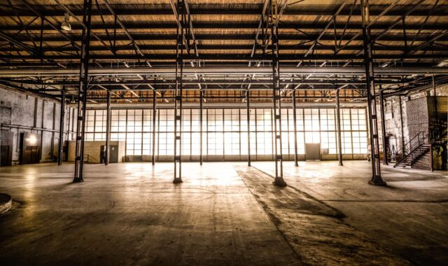
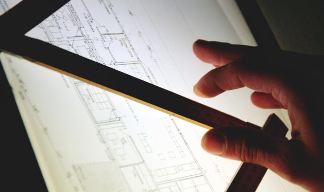
How to plan a factory building layout for safer flow and future change
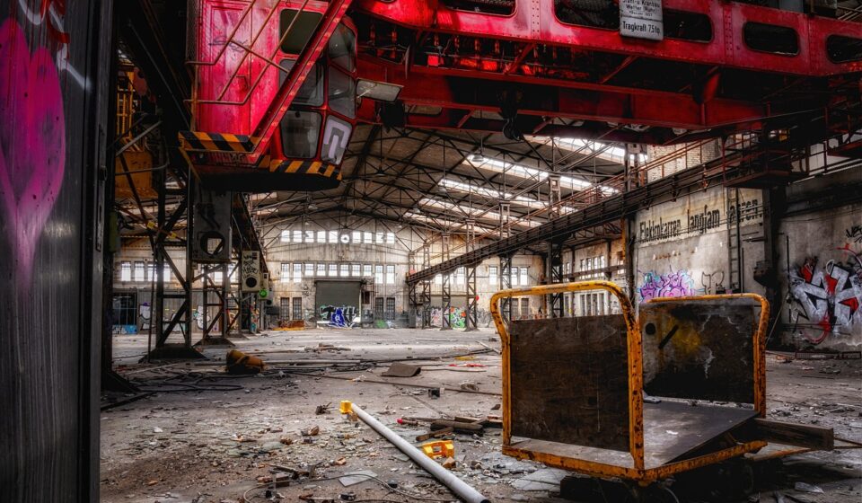
Factory building layout starts with flow, not walls
A factory building layout should be planned around movement: materials, people, equipment, information and waste. In mechanical manufacturing, the first question is not simply how large the building should be. It is what must move from receiving to production, inspection, storage and shipping, and where those movements are likely to conflict.
A workable layout needs safe aisles, code-compliant exits, practical crane or forklift routes, maintainable utilities and room for later process changes. If planning starts with column grids and office locations before the operating flow is understood, the drawing may look efficient while still creating avoidable handling, congestion and rework once production starts.
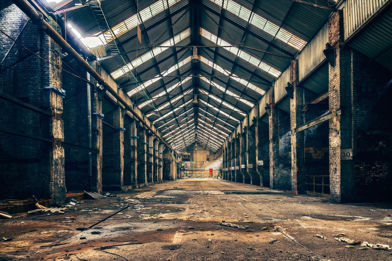
This article outlines a practical planning sequence for manufacturers, industrial property teams and project planners. It does not replace a licensed architect, fire protection engineer or local code review, but it can help decision makers ask better questions before design choices become expensive to change. More articles on production space planning can be found in the factory planning section.
Define the operating model before drawing the floor plan
The building should support the production system. A low-volume, high-mix machining plant does not need the same arrangement as a repetitive assembly plant, a fabrication shop or a spare-parts processing center. Before drawing departments on a plan, define the operating model in plain language.
- Product families: Identify which parts share machines, routes, inspection steps, tooling and packaging requirements.
- Process sequence: Map the normal route from raw material receiving to finished goods shipping, including outside processing if parts leave the site.
- Volume and batch size: Estimate peak daily movement, not only average monthly output.
- Handling method: Clarify whether parts move by forklift, pallet jack, overhead crane, cart, conveyor, automated vehicle or manual carrying.
- Quality control points: Decide where inspection, quarantine and nonconforming material areas are required.
- Service needs: List compressed air, power, exhaust, coolant, gas, water, drainage and data requirements for each process area.
A simple flow map often reveals layout risks earlier than a polished rendering. For example, if raw steel, machined parts, painted parts and finished assemblies all cross the same aisle, the plan may create traffic conflicts even when each department appears to have enough space. The U.S. Environmental Protection Agency has described value stream mapping and cellular manufacturing as lean methods for understanding material and information flow. The same planning logic applies at the building level: visualize the current or expected flow before deciding where fixed walls, pits, docks and utility trenches belong.
Choose a layout type that matches production behavior
Most factories use a combination of layout types. The right choice depends on product variety, process stability, part size, changeover frequency and the level of supervision required.
| Layout type | Typical use | Main advantage | Common risk |
|---|---|---|---|
| Process layout | Machining, welding, grinding or similar equipment grouped by function | Flexible for high-mix work | Longer travel distance and more work-in-process if routes are complex |
| Product line layout | Repetitive assembly or packaging with stable sequence | Clear flow and easier production balancing | Less flexible when product design or volume changes |
| Cellular layout | Product families that share a short sequence of machines or benches | Can reduce movement and simplify visual control | Requires careful grouping of machines, parts and skills |
| Fixed-position layout | Large equipment, heavy frames or oversized assemblies | The product stays in place while tools and workers move to it | Material staging can become crowded if not controlled |
In mechanical manufacturing, a hybrid layout is common. Heavy raw material may enter near saws or cutting equipment, then move to machining cells, fabrication zones, heat treatment, surface treatment, assembly, inspection and shipping. The objective is not to force every process into a straight line. It is to reduce unnecessary crossing, backtracking and waiting while keeping the plan realistic for equipment foundations, crane coverage, exhaust, noise and maintenance access.
Separate material flow, people flow and emergency movement
A common weakness in factory planning is treating every open area as a shared aisle. In practice, a forklift route, pedestrian walkway, emergency exit path, maintenance access lane and temporary staging zone should not automatically occupy the same space. Combining them without clear rules can increase congestion and make the building harder to manage.
Material movement
Material movement should be designed around the heaviest and most frequent flows first. Receiving docks, raw material storage, cutting areas and shipping docks often drive the largest number of vehicle movements. OSHA’s general industry requirements for material handling state that where mechanical handling equipment is used, safe clearances must be allowed for aisles, loading docks, doorways and turns, and permanent aisles and passageways must be appropriately marked. This is a performance-based requirement rather than a universal aisle-width number, so planners should confirm actual equipment dimensions, turning radius, load size and local safety requirements.
People movement
Pedestrian routes should connect entrances, locker rooms, offices, production cells, restrooms, canteens and emergency exits without forcing workers through high-traffic forklift areas. When pedestrian and vehicle paths must intersect, crossings should be visible, limited and easy to understand. Marked walkways, barriers, gates, mirrors, lighting and speed control may be needed, but these controls work best when the basic layout already reduces conflict.
Emergency movement
Emergency routes require separate attention because production convenience cannot override safe egress. The International Building Code classifies many manufacturing and fabrication operations under factory industrial occupancies, while high-hazard or storage uses may trigger different requirements. NFPA life-safety provisions and locally adopted building and fire codes address exit access, travel distance, exit capacity, door swing, signage and related issues. These items should be reviewed before equipment is fixed in place, because relocating a machine is usually easier than redesigning exits after installation.
Plan building zones around constraints that are difficult to move
Some layout elements can change over time. Benches, racks, carts and light partitions can often be adjusted. Other elements are expensive or disruptive to move. These fixed or semi-fixed constraints should shape the early factory building layout.
- Columns and structural spans: Column spacing affects crane travel, rack layout, equipment placement and the ability to create future cells.
- Floor capacity and flatness: Heavy machines, storage racks, forklifts and automated systems may require specific slab design, reinforcement or tolerances.
- Docks and yard access: Truck turning, dock quantity, trailer staging and security gates should be checked against real delivery patterns.
- Overhead cranes and lifting coverage: Crane runways, hook height and lift paths can determine whether large components move safely and directly.
- Utilities: Electrical distribution, compressed air, extraction, chilled water, drainage and process gases should allow maintenance access and expansion.
- Fire protection and hazardous areas: Sprinklers, fire separation, flammable storage, battery charging, paint or coating areas and dust-producing operations may require specialist review.
The layout team should distinguish between production preferences and design constraints. Placing a finishing area in the middle of the plant may shorten travel distance, but it could complicate ventilation, fire separation, waste handling or environmental controls. Locating offices beside production may improve communication, but noise, vibration, visitor access and emergency separation still need to be evaluated.
Use sizing rules that include buffers, not just equipment footprints
Equipment footprints are only the starting point. A machine’s real space demand includes operator position, door swing, chip removal, tool storage, electrical cabinets, maintenance access, guarding, in-process material, scrap bins and movement around the machine. If planners size a department only by adding equipment rectangles, the factory may be full on day one.
A more reliable approach is to build a space program by activity. Each process area should include the following allowances where relevant: See also: buying guides.
- Operating envelope around each machine or workbench
- Maintenance access for service panels, motors, filters, pumps and lifting points
- Incoming and outgoing material positions
- Temporary work-in-process limits
- Inspection and measurement space
- Tooling, fixtures and consumables
- Scrap, waste and returnable packaging
- Safety clearance, guarding and lockout access
Buffers should be intentional, visible and limited. Too little buffer creates blocked aisles and unstable schedules. Too much buffer hides problems and consumes expensive floor area. A good layout makes normal material positions obvious, so supervisors can see when production is drifting away from the plan.
Design for future change without oversizing everything
Future flexibility is not the same as buying unused space everywhere. A better strategy is to protect the parts of the factory that are hardest to change and make the rest modular. For example, a building may use a structural grid that allows future cells, utility headers that can be extended, clear expansion zones at the end of production lines, and dock positions that can handle higher throughput. At the same time, it can avoid overbuilding every storage area or making every aisle wider than necessary.
Useful flexibility measures include:
- Expansion logic: Decide whether future growth will extend the production line, duplicate cells, add shifts or add a new building bay.
- Utility reserves: Provide realistic spare capacity and accessible distribution routes rather than buried systems that require shutdowns to modify.
- Modular support areas: Use movable partitions, standardized benches and mobile storage where process control allows.
- Clear change rules: Require review before equipment, racks or staging zones are moved into aisles or exit paths.
- Data-ready planning: Reserve space and pathways for sensors, quality stations, production displays and future automation interfaces.
The most resilient layouts usually combine disciplined flow with controlled adaptability. A plant that is too rigid may struggle with new products. A plant that is too open may gradually turn into informal storage. The layout should make the preferred way of working easy and the unsafe workaround difficult.
A practical factory building layout checklist
The following checklist can help teams review a concept layout before moving into detailed design. It is not a code checklist, but it highlights decisions that often affect cost, safety and operating performance.
- Has the main material route been mapped from receiving to shipping?
- Are high-frequency flows separated from occasional maintenance movement where practical?
- Do forklifts, carts, cranes and pedestrians have clearly defined routes?
- Are permanent aisles, passageways and loading areas sized for actual handling equipment and loads?
- Have exit routes, travel paths and door locations been reviewed before equipment placement is finalized?
- Are inspection, quarantine and rework areas visible and controlled?
- Is work-in-process space planned by process need rather than left to occupy open aisles?
- Can heavy equipment be installed, serviced and replaced without excessive disruption?
- Are utilities accessible for maintenance and future changes?
- Does the layout protect possible expansion areas from being consumed by short-term storage?
A factory building layout is successful when it supports production every day, not just when it looks organized in a drawing. Start with flow, verify safety and code constraints, size the real working envelope, and preserve options for change. Those steps reduce the risk of building a facility that must be corrected immediately after it opens.
Frequently asked questions
What is the first step in factory building layout planning?
The first step is mapping the operating flow. Planners should understand product families, process routes, handling methods, inspection points and storage needs before fixing walls, docks, columns or offices.
How much aisle space does a factory need?
There is no single aisle width that fits every factory. Aisle space depends on forklifts, load dimensions, turning radius, pedestrian separation, storage methods, emergency access and locally applicable rules. OSHA requires safe clearances where mechanical handling equipment is used and requires permanent aisles and passageways to be appropriately marked.
Should production offices be inside the factory or separate?
Both options can work. Offices near production improve communication and supervision, but planners must consider noise, vibration, air quality, visitor control, fire separation and safe access. Sensitive engineering or quality functions may need quieter, cleaner space.
What makes a factory layout flexible?
A flexible layout uses adaptable cells, accessible utilities, sensible column spacing, protected expansion zones and clear change-control rules. Flexibility should support planned growth, not create uncontrolled open space that becomes storage.
Who should review a factory layout before construction?
A concept layout should be reviewed by operations, maintenance, safety, quality, logistics, facilities engineering and qualified design professionals. Building, fire, environmental and occupational safety requirements should be confirmed with the authorities and specialists responsible for the project location.