How to choose a soldering machine for electronics manufacturing
Start with the soldering process, not the machine name
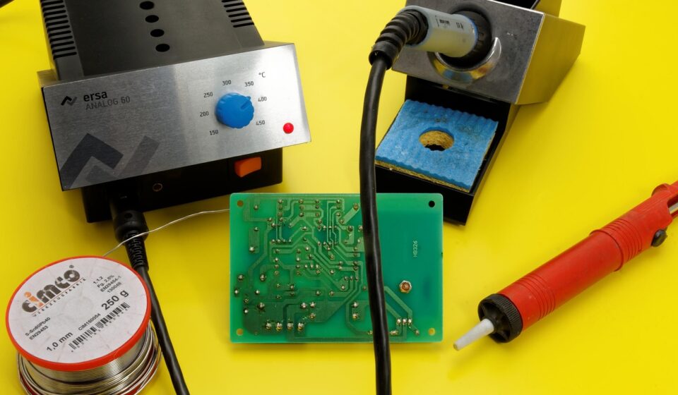
Select a soldering machine around the assembly process it has to control: surface-mount reflow, through-hole wave soldering, selective soldering, robotic point soldering, hot-bar bonding, or a combination of these methods. The right choice depends on board design, component mix, production volume, solder alloy, flux chemistry, inspection requirements, and the amount of changeover the line must support. For electronics manufacturers, the key question is not simply whether a machine can melt solder. It is whether it can repeatedly produce acceptable joints while protecting nearby components, controlling residues, supporting traceability, and fitting the factory workflow.
That is why two machines with similar published heating power or conveyor width can perform very differently on the shop floor. A high-volume SMT line may need stable thermal profiling and nitrogen capability. A mixed-technology board with connectors may need selective soldering to avoid reheating components that have already passed through reflow. A low-volume repair or cable assembly cell may be better served by programmable robotic soldering than by a conveyorized system.
For related manufacturing equipment topics, visit the machine tools section.
Main types of soldering machine
The term soldering machine covers several equipment families. Each is designed for a different joining problem, so comparing machines only by price or footprint can lead to a poor specification.
| Machine type | Typical use | Main process controls | Common limitation |
|---|---|---|---|
| Reflow oven | SMT components on printed circuit boards | Zone temperature, conveyor speed, atmosphere, thermal profile | Not ideal for many heat-sensitive through-hole parts unless designed for pin-in-paste |
| Wave soldering machine | High-volume through-hole or mixed assemblies | Flux application, preheat, solder pot temperature, wave height, conveyor angle | Less flexible for dense mixed-technology boards with bottom-side SMT components |
| Selective soldering machine | Localized soldering of through-hole pins after SMT reflow | Flux spot size, preheat, nozzle path, dwell time, solder height | Cycle time can be longer than wave soldering for very large pin counts |
| Robotic soldering machine | Point-to-point joints, wires, terminals, repair, small batches | Tip temperature, feed rate, dwell time, angle, robot path | Requires careful tip maintenance and programming discipline |
| Hot-bar or pulse-heated system | Flex circuits, ribbon cables, displays, tabs, and localized joints | Pressure, heat pulse, time, alignment | Application-specific tooling can limit flexibility |
In many electronics factories, more than one soldering method is used on the same product family. A common sequence may include solder paste printing, pick-and-place, reflow, inspection, and then selective soldering for connectors or odd-form components that cannot pass through the first reflow step.
Match the machine to board design and production volume
The first specification should come from the product, not the catalog. Board size, component height, thermal mass, copper area, connector location, keep-out areas, and pallet requirements all affect machine choice. A process that works well on a simple single-sided board may fail on a dense assembly with heavy copper planes or uneven heat distribution.
Surface-mount assemblies
For SMT work, the reflow oven is usually the central soldering machine. Buyers should evaluate thermal uniformity, number of heating zones, cooling capacity, conveyor stability, profile storage, and whether the oven can support the solder paste manufacturer’s recommended profile. Lead-free solder alloys generally have a tighter thermal process window than older tin-lead processes, so profiling should be treated as a routine production activity rather than a one-time setup task.
Through-hole and mixed-technology boards
Wave soldering remains useful for high-volume through-hole assemblies when the layout, masking, and component clearances support the process. Dense mixed-technology boards often move manufacturers toward selective soldering. Selective systems reduce thermal exposure across the full board and can solder chosen pins after SMT reflow, but they require accurate programming, suitable nozzle selection, and stable flux control.
Low-volume or high-mix work
For high-mix production, robotic soldering can be more practical than a conveyorized line. Recipes can be changed by program, and the same cell may handle terminals, wires, odd-shaped joints, and small batches. The tradeoff is that quality depends heavily on joint access, solder wire feed consistency, tip condition, fixturing, and well-defined acceptance criteria.
Process control matters more than maximum temperature
Machine comparisons often highlight maximum temperature, wattage, or solder pot capacity. Those figures matter, but they do not prove process capability. A good soldering machine must control the variables that actually form the joint.
- Heat transfer: The machine must deliver enough heat to the joint without overheating components, laminate, insulation, or nearby soldered areas.
- Time at temperature: Too little time can cause incomplete wetting; too much time can damage parts or increase residue problems.
- Flux behavior: Flux activation, evaporation, residue, and compatibility with cleaning or no-clean processes must be understood before production release.
- Mechanical stability: Conveyor vibration, board sag, pallet accuracy, nozzle alignment, and robotic repeatability all affect joint formation.
- Atmosphere: Nitrogen may reduce oxidation in some reflow or selective soldering processes, but it adds cost and should be justified by yield, wetting, or defect data.
Industry standards help define what the finished joint and the related process controls should achieve. IPC J-STD-001 is widely referenced for soldered electrical and electronic assemblies, while IPC-A-610 is commonly used for acceptability of electronic assemblies. These standards do not remove the need for internal process validation, but they give buyers and manufacturing teams a common language for requirements, inspection, and workmanship classes.
Compliance, safety, and workplace controls
Soldering equipment decisions also involve regulatory and safety constraints. In markets affected by EU RoHS requirements, lead in electrical and electronic equipment is restricted at the homogeneous-material level, subject to defined exemptions. This is one reason lead-free soldering, compatible component finishes, and controlled thermal profiles are routine in many electronics lines.
Workplace exposure should be considered early. OSHA identifies lead exposure as a potential occupational issue when lead-containing materials are used, and its general industry lead standard includes an action level based on an eight-hour time-weighted average. Even when lead-free solder is used, flux fumes may still be relevant. NIOSH recognizes rosin-core solder pyrolysis products as a chemical exposure category, and flux decomposition products may irritate the respiratory system for some workers.
For machine selection, the buyer should answer practical questions before ordering:
- Does the equipment include fume capture points suitable for the actual process?
- Can local exhaust ventilation be connected without disrupting heat balance or machine access?
- Are solder pots, dross handling points, flux tanks, and maintenance areas designed for safe service?
- Does the production plan require leaded and lead-free process segregation?
- Are operators trained for flux handling, tip cleaning, residue control, and personal hygiene where metals are involved?
Safety features are part of the equipment specification, not optional extras. Guards, interlocks, emergency stops, thermal insulation, clear maintenance access, and documentation should be evaluated with the same seriousness as throughput. See also: buying guides.
Traceability and data integration are becoming purchase criteria
Modern soldering machines increasingly operate inside connected production lines. Traceability is valuable when a manufacturer needs to link a product serial number to recipe version, thermal profile, process alarms, inspection results, operator actions, and rework history. This is especially important in automotive, medical, industrial controls, aerospace, and other reliability-sensitive sectors.
For SMT line communication, IPC-HERMES-9852 is used as a machine-to-machine communication standard and is positioned as a successor to older SMEMA-style handover communication. IPC CFX is used for broader factory data exchange. Not every production cell needs full digital integration on day one, but a new soldering machine should still be evaluated for recipe control, barcode or board-ID handling, alarm logging, data export, and compatibility with the manufacturer’s MES or quality system.
Traceability should not mean collecting data without a production purpose. Useful data should answer specific questions: which recipe was used, whether the board followed the approved route, whether a temperature profile drifted, whether a nozzle clog alarm occurred, and whether a changeover was completed correctly.
Total cost of ownership is broader than purchase price
The lowest-priced soldering machine can become expensive if it increases defects, slows changeover, consumes excessive nitrogen, requires hard-to-source spare parts, or lacks service support. A more realistic comparison should include operating cost and production risk.
- Consumables: solder alloy, solder wire, flux, nozzles, tips, filters, cleaning materials, pallets, and masking fixtures.
- Energy and utilities: heating power, compressed air, nitrogen, extraction, cooling, and standby modes.
- Maintenance: pot cleaning, dross removal, pump service, conveyor calibration, thermocouple checks, tip replacement, and software backup.
- Quality cost: bridges, insufficient solder, opens, solder balls, lifted pads, component damage, residues, rework, and scrap.
- Changeover cost: recipe loading, fixture exchange, nozzle changes, board support adjustment, and first-article approval.
- Support risk: availability of spare parts, remote diagnostics, local service capability, documentation, and operator training.
A practical buying process includes sample board trials, thermal profiling, inspection of cross-sections or microsections when reliability demands it, and a written process window before final acceptance. If a supplier cannot demonstrate the machine on representative assemblies, the buyer should treat published specifications cautiously.
A practical checklist before ordering
Before issuing a purchase order, manufacturing teams should document the requirements that directly affect process capability. The checklist below helps compare vendors without turning the decision into a simple price contest.
- Define the assemblies by board size, thickness, copper weight, component height, solder alloy, flux type, and expected annual volume.
- Identify the soldering process required for each joint family: SMT, through-hole, connector pins, wires, terminals, shields, or flex circuits.
- Confirm the applicable workmanship class, customer requirements, and internal inspection standard.
- Request evidence of thermal stability, repeatability, and process logging under realistic production conditions.
- Check whether ventilation, nitrogen, compressed air, power, and floor space match the facility.
- Review maintenance tasks, expected wear parts, service intervals, software backup, and spare-parts lead time.
- Run representative boards, not only demonstration coupons, during the acceptance test.
- Document recipe limits, inspection criteria, cleaning requirements, and operator responsibilities before release.
The strongest purchase decision usually combines engineering trials with production reality. A machine that looks slower on paper may be the better choice if it reduces rework, shortens changeover, improves traceability, or makes maintenance more predictable.
Frequently asked questions
What is the difference between wave soldering and selective soldering?
Wave soldering exposes the underside of a board to a moving wave of molten solder, making it efficient for suitable through-hole assemblies. Selective soldering applies flux and solder only to programmed locations, which makes it better for mixed-technology boards where nearby components must be protected from broad heat exposure.
Is a reflow oven considered a soldering machine?
Yes. A reflow oven is a soldering machine used mainly for SMT assembly. It heats solder paste through a controlled thermal profile so the paste melts, wets the pads and component terminations, and then solidifies during cooling.
When is robotic soldering a good choice?
Robotic soldering is useful for high-mix, low- to medium-volume production, wire and terminal soldering, and joints that can be accessed consistently by a programmed iron or laser. It is less suitable when the joint geometry changes frequently without good fixturing or when cycle time is the dominant requirement.
Does lead-free solder require a different machine?
Not always, but the machine must support the required process window. Lead-free alloys often need different temperature profiles and tighter control of wetting, oxidation, and component heat exposure. Existing equipment should be validated before it is used for lead-free production.
What should be verified during machine acceptance?
Acceptance should verify solder joint quality, repeatability, thermal profile stability, safety functions, recipe control, data logging, maintenance access, and the ability to run representative boards. A trial that uses only simple samples may not reveal problems with real assemblies.