Manufacturing tooling explained for process planning and part quality
What manufacturing tooling includes
Manufacturing tooling is the set of dedicated or semi-dedicated tools used to make, hold, form, cut, locate, assemble, and inspect parts during production. It includes molds, dies, jigs, fixtures, cutting tools, gauges, templates, workholding devices, and, increasingly, additively manufactured tooling. Effective tooling does more than increase production speed. It helps preserve the design intent of the part, reduces variation between operators or machines, and makes inspection more repeatable. Poor tooling has the opposite effect: a part that looks manufacturable on paper can become slow, inconsistent, or costly to control on the shop floor.
For process planners, the main question is not only, “What tool is needed?” It is, “What tool is justified by the part geometry, tolerance, volume, material, change risk, and inspection method?” That question should be answered before production release, not after scrap, rework, or late engineering changes reveal a tooling gap.
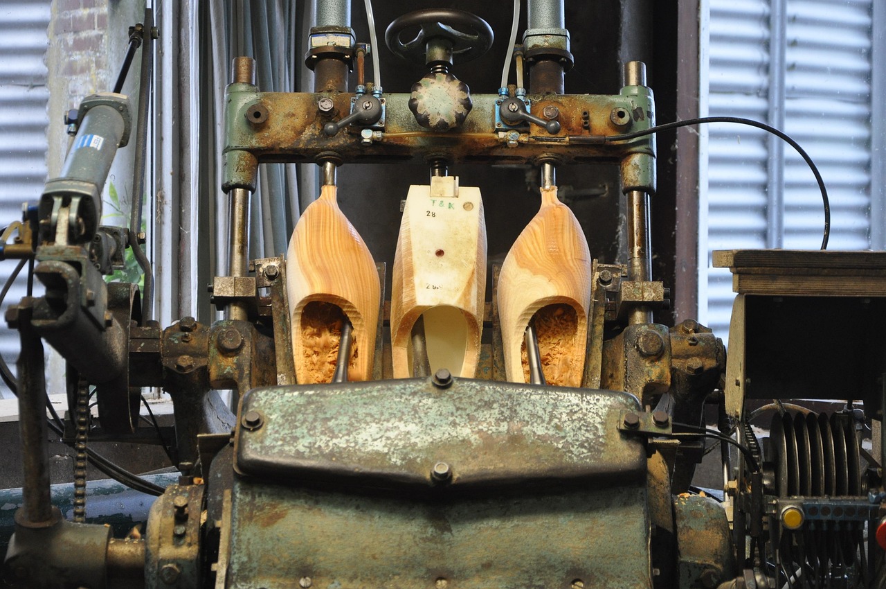
Why tooling decisions affect cost, lead time, and quality
Tooling is often treated as a one-time setup cost, but its influence continues for the full production life of a part. A fixture that locates from unstable surfaces can create dimensional variation even when the machine is accurate. A stamping die with poor wear allowance may run well during sampling but drift after repeated production cycles. A mold with inadequate cooling can extend cycle time and make shrinkage or warpage harder to control.
In practical terms, tooling affects three production outcomes at the same time:
- Cost: Tooling can reduce labor and cycle time, but overbuilt tooling can make low-volume production uneconomical.
- Lead time: Dedicated tooling may take longer to design, build, debug, and approve than the part itself.
- Quality: Tooling determines how consistently a part is located, supported, formed, cut, cooled, or measured.
Public guidance from organizations such as NIST MEP also highlights the role of modern tooling methods, including additive manufacturing, in reducing tool development time, enabling conformal cooling in injection molds, and creating molds or cores directly from digital designs. These benefits are application-specific, so they should be evaluated against material requirements, tolerance needs, durability, and validation demands.
Main types of manufacturing tooling
The term manufacturing tooling covers several tool families. The right category depends on whether the operation removes material, forms material, holds the workpiece, guides the process, or verifies the result.
| Tooling type | Typical use | Key planning concern |
|---|---|---|
| Molds | Injection molding, casting, rubber molding, composite forming | Thermal control, shrinkage, cavity finish, venting, maintenance |
| Dies | Stamping, blanking, drawing, forging, extrusion | Material flow, clearance, wear, press compatibility, die protection |
| Jigs | Guiding a tool or operation, such as drilling or assembly alignment | Repeatability, access, operator loading, mistake-proofing |
| Fixtures | Holding and locating a part during machining, welding, inspection, or assembly | Datum strategy, clamping force, distortion, chip or weld access |
| Cutting tools | Milling, turning, drilling, broaching, grinding | Tool life, coating, geometry, coolant, material compatibility |
| Gauges and inspection tools | Checking dimensions, location, fit, or functional acceptance | Measurement uncertainty, calibration, traceability, operator method |
| Soft or prototype tooling | Early runs, bridge production, low-volume validation | Limited life, lower cost, faster changes, controlled expectations |
| Modular tooling | Flexible fixturing, repeat jobs, changing product families | Setup control, stiffness, documentation, repeat setup accuracy |
A useful distinction is between tooling that creates the part shape and tooling that controls the process. Molds and dies directly shape the part. Fixtures, jigs, and gauges may not become part of the product, but they strongly influence whether the process can repeatedly meet the drawing.
How tooling should fit into the process planning workflow
Manufacturing tooling should be planned as part of the complete production system. Treating it as a late purchasing item is one of the fastest ways to create hidden risk. A stronger workflow starts with design intent and ends with documented tool release.
- Review part geometry and tolerances. Identify critical dimensions, datum features, thin walls, hard-to-reach surfaces, and cosmetic requirements.
- Match tooling to the manufacturing process. A machined part may need custom workholding, while a molded part may need careful gate, cooling, and ejection planning.
- Check access and loading. Tools must allow cutters, electrodes, clamps, robots, operators, and inspection probes to reach the required areas safely.
- Define the datum strategy. The tooling should locate from features that represent the design and inspection intent, not only from convenient surfaces.
- Plan wear and maintenance. Inserts, cutting edges, guide pins, bushings, ejectors, and high-contact surfaces should be replaceable or inspectable where appropriate.
- Validate before full release. Trial runs, first article inspection, capability checks, and documented corrections help separate tool issues from machine, material, or operator issues.
- Control revisions. Tool drawings, setup sheets, programs, gauges, and inspection plans should change together when the product design changes.
This workflow is especially important when readers compare tooling with broader manufacturing processes, because the same part may require different tooling logic in machining, casting, molding, stamping, welding, or additive manufacturing.
Conventional, modular, and additive tooling compared
No tooling approach is automatically better in every situation. Conventional hard tooling, modular tooling, and additive tooling solve different production problems.
| Approach | Where it fits | Limitations |
|---|---|---|
| Conventional hard tooling | High-volume production, tight repeatability, long tool life, demanding forming or molding loads | Higher upfront cost, longer build time, more expensive design changes |
| Modular tooling | Short runs, recurring product families, flexible machining or assembly setups | May be less optimized than dedicated tools; setup discipline is critical |
| Additive tooling | Prototype fixtures, complex internal channels, lightweight end-of-arm tools, sand molds or cores, conformal cooling inserts | Material limits, surface finish, qualification needs, thermal and wear performance must be verified |
Conventional hard tooling remains important where production volume, pressure, heat, abrasion, or dimensional stability justify a robust tool build. In these cases, the cost of tool design and machining is spread across a larger number of parts, and the tool’s durability becomes part of the economic case.
Modular tooling is often useful when product variety is high or demand is uncertain. It allows faster reconfiguration, but it also requires clear setup documentation. A modular fixture that can be assembled many ways can also be assembled incorrectly unless locators, stops, torque values, and inspection checks are controlled.
Additive tooling is valuable when geometry is difficult or slow to make conventionally. NIST MEP has pointed to examples such as conformal cooling in injection molds and printed sand molds or cores. The engineering advantage comes from design freedom, but the tooling still needs realistic validation. A printed fixture may be excellent for an ergonomic assembly station but unsuitable for high-temperature, high-wear, or high-clamping-force service unless the material and design have been proven.
Common tooling risks and how to control them
The most expensive tooling problems are often not dramatic failures. They are smaller mismatches between the tool, the part drawing, and the production method.
Unclear datum transfer
If a fixture locates a part from one set of surfaces while inspection evaluates another, the process can appear unstable even when each individual operation is repeatable. Tooling design should reflect the drawing’s functional datum structure wherever practical. When process datums must differ from inspection datums, the difference should be understood and controlled. See also: buying guides.
Tooling built before the design is stable
Early tooling can shorten schedules, but only if change risk is managed. For unstable designs, soft tooling, modular tooling, or replaceable inserts can reduce the cost of changes. For stable, high-volume products, hard tooling may be justified earlier.
Insufficient gauge and measurement control
Inspection tooling must be treated as part of the quality system. ISO 9001 guidance on monitoring and measuring resources emphasizes fitness for purpose and documented evidence where measurement results are used to verify conformity. In practical shop terms, gauges need identification, calibration or verification rules, and a clear method of use.
Wear that is not visible during sampling
A tool can pass first article inspection and still be weak for production. Dies, mold components, cutting tools, drill bushings, locating pins, and clamps wear over time. Planning should include inspection intervals, spare components, lubrication, cleaning, and replacement criteria.
Tooling ownership and revision gaps
When tooling is built by one supplier and used by another, ownership, storage, maintenance, repair authority, and design data access should be defined. This is particularly important for molds, dies, gauges, and fixtures that may move between prototype, bridge, and production suppliers.
A practical checklist before releasing tooling
Before approving manufacturing tooling for production, teams should ask practical questions that connect engineering, production, quality, and purchasing.
- Does the tool support the part in a way that avoids distortion during clamping, forming, welding, machining, or cooling?
- Are critical features located from appropriate datums?
- Can operators load and unload the tool consistently and safely?
- Are chips, flash, burrs, weld spatter, coolant, or debris likely to interfere with location?
- Can the tool be inspected, cleaned, maintained, and repaired without excessive downtime?
- Are wear components replaceable, and are spare parts defined?
- Does the tool revision match the product drawing, process plan, CNC program, inspection plan, and gauge design?
- Has the tool been validated with actual production material, not only ideal samples?
- Is there a plan for low-volume, bridge, or engineering-change scenarios?
The best tooling plans make trade-offs visible. A low-cost fixture may be reasonable for a short run if the tolerances are forgiving. A complex hardened fixture may be justified when variation would create scrap, downtime, or field failures. The decision should follow the process risk, not habit.
Frequently asked questions
What is manufacturing tooling?
Manufacturing tooling refers to the tools used to make, hold, form, guide, cut, assemble, or inspect parts. Common examples include molds, dies, jigs, fixtures, cutting tools, gauges, and templates.
What is the difference between a jig and a fixture?
A fixture primarily holds and locates the workpiece. A jig also guides the tool or operation. In modern shops the terms are sometimes used loosely, but the distinction still matters when designing repeatable machining, drilling, assembly, or inspection processes.
Why can tooling be expensive?
Tooling cost comes from engineering time, precision machining, material selection, heat treatment, surface finishing, trial runs, corrections, and validation. The cost may be justified when the tool reduces cycle time, scrap, variation, or labor over a long production run.
When is soft tooling a good choice?
Soft tooling is useful for prototypes, bridge production, market testing, or designs that may still change. It usually has lower upfront cost and shorter lead time than hard tooling, but it may have limited life, lower durability, or narrower process capability.
Can additive manufacturing replace traditional tooling?
Additive manufacturing can replace or improve some tooling, especially prototype fixtures, lightweight grippers, sand molds, cores, and tooling with internal channels. It does not replace traditional tooling in every case. Heat, load, wear, tolerance, surface finish, and qualification requirements still determine whether a printed tool is appropriate.