Machined components for precision assemblies and how quality is controlled
Machined components are defined by controlled requirements, not only CNC equipment
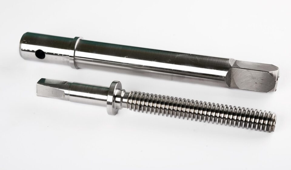
Machined components are parts made by removing material from metal, plastic, or other engineered stock until the finished geometry meets a defined specification. In precision assemblies, the value of a machined part does not come from CNC equipment alone. It comes from the way the drawing, material condition, tolerance scheme, surface requirements, heat treatment, and inspection plan work together.
A component is not automatically reliable because it was produced on a CNC mill or lathe. It becomes reliable when the features that affect fit, motion, sealing, load, and repeatability are controlled. For readers following the broader precision components category, the practical question is not simply how tight a part can be made. It is which requirements protect function without adding avoidable cost.
What makes a machined component suitable for a precision assembly
A precision assembly usually depends on several interacting features, not one dimension in isolation. A shaft may need diameter control for bearing fit, runout control for rotation, surface finish control for wear, and edge-break control for safe handling. A housing may need flatness, perpendicularity, hole position, and thread quality to align mating parts. If one of these requirements is missing or unclear, the machinist may still produce a part that looks correct, while inspection and assembly results vary from lot to lot.
The strongest specifications start with function. Features that locate, seal, rotate, slide, or carry load deserve more attention than cosmetic or clearance surfaces. That does not always mean tighter tolerances. More often, it means better tolerancing: clear datums, realistic tolerance zones, defined surface texture, and inspection methods that match the risk of the feature.
ASME Y14.5-2018 is widely used for geometric dimensioning and tolerancing in U.S.-style engineering documentation, and ASME describes it as the authoritative guideline for the design language of GD&T. The 2018 edition replaced ASME Y14.5-2009, which matters when drawings need to identify the governing standard and edition to reduce interpretation risk. (asme.org)
The specification package should remove ambiguity before machining starts
A drawing or model for machined components should answer more than the question of shape. It should define the acceptable material, critical dimensions, general tolerance rules, required finish, post-machining processes, and acceptance criteria. When these points are left to assumption, suppliers may quote different scopes even when they review the same geometry.
Material and condition
The material line should include grade, temper or condition, any required certification, and whether substitutions are allowed. For metals, machining response can change with hardness, heat treatment, residual stress, and stock form. For plastics, moisture absorption, thermal expansion, and stress relief can affect final dimensions. If the component will be plated, anodized, passivated, hardened, or coated, the drawing should state whether dimensions apply before or after that process.
Tolerances and datums
General tolerances are useful for noncritical dimensions, but they should not replace design intent. ISO 2768-1:1989 specifies general tolerances for linear and angular dimensions without individual tolerance indications, while ISO 22081:2021 addresses general geometrical and size specifications and is listed by ISO as current after review and confirmation in 2026. The practical point is that the drawing must state which system applies and where individual tolerances override the general rules. (iso.org)
Surface finish, burrs, and edges
Surface finish affects friction, sealing, fatigue life, coating adhesion, and appearance. Specifying a fine finish across every face can increase machining time without improving function. A better approach is to define finish where it matters, such as bearing seats, sliding surfaces, seal grooves, fluid passages, and cosmetic faces. Edge requirements should also be explicit. A part that is dimensionally correct but has uncontrolled burrs can still fail assembly, damage seals, contaminate equipment, or create a handling risk.
Inspection and traceability
Inspection requirements should match the part’s function and risk. A prototype bracket may need only basic dimensional checks, while a high-volume precision component may require first article inspection, in-process checks, final inspection records, material certificates, and process traceability. The goal is not paperwork for its own sake. It is to make sure the acceptance evidence is strong enough for the application.
Tighter tolerances can improve function, but they can also create avoidable cost
Tolerance is one of the main cost drivers in machining. Tight limits can require slower cutting, more stable fixturing, additional finishing operations, controlled temperature, higher inspection effort, or scrap when process variation approaches the tolerance band. The cost is justified when the requirement protects function. It becomes waste when a tight tolerance is applied to a noncritical surface because of habit or copied drawing notes.
Machining error is also not a single-cause problem. NIST research on closed-loop machining describes part fabrication errors as a combination of machine tool geometric errors and other contributors. In everyday production, those contributors can include tool wear, workholding deflection, thermal growth, stock variation, programming assumptions, measurement uncertainty, and operator decisions. (nist.gov)
For this reason, practical tolerance design separates critical-to-function features from supporting geometry. A bearing bore, locating dowel hole, or sealing face may need a narrow tolerance and a defined datum relationship. A clearance pocket, cover profile, or noncontact surface may allow a wider tolerance without reducing assembly performance. This selective approach improves manufacturability while keeping quality focused on the features that matter.
| Decision area | What to define | Why it matters |
|---|---|---|
| Functional features | Fits, datums, positions, runout, flatness, and surface finish | Controls assembly alignment, motion, sealing, and load paths |
| Noncritical features | General tolerances and cosmetic limits | Avoids unnecessary machining and inspection cost |
| Post-processing | Heat treatment, coating, plating, passivation, or anodizing | Prevents dimensional disputes before and after secondary operations |
| Inspection scope | First article, sampling plan, CMM report, or certificate needs | Aligns acceptance evidence with part risk |
Quality control starts before the first chip is cut
Quality control for machined components should begin with design review and manufacturing planning, not final inspection alone. A supplier or manufacturing team should review whether datum structures are practical, tool access is realistic, tolerances can be measured, and material or post-processing steps could distort the part. A requirement that cannot be measured consistently is not a strong requirement, even if it looks precise on a drawing.
Before production, manufacturability review can identify common issues: deep pockets that require long tools, thin walls that may deflect, threaded holes too close to edges, internal corners that require impossible sharp radii, or surface finishes specified in areas that are inaccessible after setup. These issues are easier to solve before programming, fixturing, and material purchasing. See also: buying guides.
During production, quality control usually combines first-piece inspection, tool wear monitoring, in-process measurement, and final verification. For complex components, coordinate measuring machines, optical systems, surface roughness instruments, thread gauges, plug gauges, and functional gauges may all play a role. The best inspection method depends on the feature type. A CMM may be appropriate for position and profile, while a functional gauge may be more efficient for repeated assembly-critical checks.
ISO 9001:2026, released by ISO in September 2026, is a quality management system standard rather than a part tolerance standard. For machined components, its relevance is process discipline: documented responsibilities, controlled records, corrective action, and continual improvement. It does not by itself prove that a part meets a drawing; the drawing, inspection plan, and acceptance records still do that work. (iso.org)
Sourcing machined components now requires technical and supply-chain judgment
Buying machined components is no longer only a price comparison. Manufacturing buyers also consider lead time, supply continuity, regional capacity, inspection capability, material availability, and communication quality. A low quote can become expensive if it depends on unclear assumptions, long transport routes, limited inspection evidence, or repeated drawing questions after the order is placed.
Deloitte’s 2026 manufacturing outlook identifies smart manufacturing, digital supply-chain tools, investment, aftermarket services, and talent as major themes for manufacturers. For precision components, that context supports a practical conclusion: buyers benefit from suppliers that can combine machining capability with digital documentation, responsive planning, and disciplined quality systems, especially when demand, materials, and trade conditions are uncertain. (deloitte.com)
Sourcing decisions should still be evidence based. A supplier’s equipment list is useful, but it is not enough. The more important questions are whether the supplier understands the drawing standard, can hold the critical features, can measure them reliably, and can communicate exceptions before production. For high-risk components, buyers should request a sample plan, first article report, material documentation, and clarification of how nonconforming parts will be handled.
A practical checklist before releasing a machined component
Before sending a drawing or model for quotation, engineers and buyers can reduce risk by checking whether the specification answers the most common manufacturing questions. The goal is not to make the document longer. The goal is to make the intent clearer.
- Identify the component’s critical functions, such as locating, rotating, sealing, sliding, or carrying load.
- Apply tight tolerances only where they protect those functions.
- State the governing drawing and tolerancing standard, including the edition when necessary.
- Define material grade, condition, and whether substitutions are permitted.
- Clarify whether dimensions apply before or after coating, plating, heat treatment, or other secondary processes.
- Specify surface finish and edge requirements only where they are functionally or cosmetically necessary.
- Make datum structures logical for both manufacturing and inspection.
- Confirm that critical features can be measured with available equipment and repeatable methods.
- Request inspection records that match the risk level of the component.
- Resolve ambiguous notes before quotation so suppliers price the same scope.
This checklist keeps the discussion focused on function, repeatability, and acceptance criteria. It also makes cost reduction more productive. Instead of asking the supplier to guess where savings are possible, the team can identify noncritical tolerances, simplify setups, adjust material choices, or revise features that are difficult to machine but not essential to performance.
Frequently asked questions
Are machined components the same as CNC parts?
Not exactly. Many machined components are made on CNC equipment, but the term machined component focuses on the finished part and its requirements. CNC describes one method of producing it. Manual machining, turning, milling, grinding, EDM, and secondary finishing may also be part of the route, depending on geometry and tolerance needs.
What tolerance should be used if none is shown on the drawing?
The answer depends on the drawing notes and the standard referenced by the organization. If no general tolerance standard or title block tolerance is stated, the requirement is ambiguous and should be clarified before machining. Assuming a shop default may lead to disputes when the part is inspected or assembled.
When is GD&T needed for machined components?
GD&T is most useful when part function depends on relationships between features, such as position, orientation, flatness, profile, runout, or datum-controlled assembly. It is especially helpful when plus-minus dimensions do not clearly describe how the part should locate, mate, or move in the final product.
How can cost be reduced without lowering quality?
Cost can often be reduced by widening tolerances on noncritical features, simplifying setups, allowing practical internal radii, avoiding unnecessary fine finishes, clarifying inspection scope, and reviewing whether post-processing affects dimensions. The key is to protect critical functions while removing requirements that do not improve performance.
What inspection records should buyers request?
For simple low-risk parts, a basic dimensional report may be enough. For precision or assembly-critical machined components, buyers may need first article inspection, CMM reports, material certificates, surface finish checks, heat-treatment records, coating certificates, and documented disposition of any deviations. The required records should match the risk of the application.