How to specify precision turned components for reliable fit, cost and inspection
What precision turned components are
Precision turned components are machined parts made mainly by rotating bar stock or a workpiece against cutting tools on lathes, CNC turning centers or Swiss-type machines. They are commonly used where round, cylindrical, threaded, grooved or concentric features must fit reliably with mating parts. The engineering question is not only whether a part can be turned. It is whether the drawing, tolerance scheme, material, surface finish and inspection method are clear enough for repeatable production.
A well-specified turned part reduces rework, avoids unnecessarily tight tolerances and gives buyers a stronger basis for comparing machining routes and quotations.
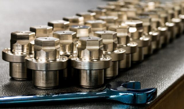
Typical examples include shafts, pins, spacers, bushings, fittings, sleeves, connectors, valve elements, fasteners and small motion-control parts. Many are mostly rotational, but modern turn-mill machines can also add flats, cross holes, slots, milled faces and off-axis features in the same setup.
For broader context on machined and precision components, the turning process should be viewed as part of a complete product definition system, not as an isolated cutting operation.
Where CNC turning creates value and where it has limits
CNC turning is strongest when a component has a central axis, repeated diameters, shoulders, grooves, threads, tapers or close concentricity requirements. Because the workpiece rotates, turned geometry can often be produced efficiently with good roundness and coaxial control, provided the machine, workholding and toolpath are appropriate.
Swiss-type turning is often considered for small-diameter, slender or high-volume components. In this method, the bar is supported close to the cutting point, which helps reduce deflection on long, narrow parts. Conventional fixed-headstock turning may be more suitable for larger diameters, shorter workpieces, lower complexity or parts that do not benefit from guide-bushing support. Turn-mill equipment can reduce secondary operations when a part also needs flats, holes or milled details.
Turning is not automatically the lowest-cost route for every part that looks round. Thin walls, deep bores, interrupted cuts, difficult materials, very fine surface finishes and extensive deburring can increase cycle time or require secondary operations. For low volumes, setup, programming and inspection time may dominate the unit cost. For production volumes, tool life, chip control, bar-feed stability and in-process measurement become more important.
Specifications that control cost and quality
The most common sourcing problem is an under-defined drawing, not a lack of machining vocabulary. Precision turned components should be specified around function. A noncritical spacer face does not need the same tolerance strategy as a bearing seat, sealing diameter or threaded interface.
Over-tolerancing increases inspection burden and may force slower cuts, extra finishing passes or unnecessary grinding. Under-tolerancing can lead to assembly failures that cost more than the machining itself. The practical goal is to make critical features clear and leave noncritical features with suitable general tolerances.
Material and bar stock
Material selection affects machinability, corrosion resistance, strength, burr formation, thermal behavior and finishing response. Stainless steels such as 303, 304, 316 and precipitation-hardening grades are not interchangeable from a machining or application standpoint. Aluminum alloys can machine quickly, but strength, anodizing behavior and scratch sensitivity differ by grade. Brass often machines cleanly for fittings and electrical parts, while titanium and certain nickel alloys may require slower speeds, rigid setups and careful heat control.
The specification should identify the material grade, applicable standard, heat-treatment condition if needed, and whether material certification is required. Bar stock diameter, straightness and availability can also affect yield and lead time, especially for long or small-diameter parts.
Tolerances, fits and GD&T
Dimensional tolerance should match the role of each feature. ISO 286 is commonly associated with hole and shaft fits, while ISO 2768 is often used as a reference for general tolerances where individual dimensions are not called out. ASME Y14.5 is widely used for geometric dimensioning and tolerancing, including form, orientation, location and profile controls. The exact standard and revision should be stated in the drawing or purchasing specification instead of being assumed.
For turned parts, pay close attention to concentricity-related requirements, runout, perpendicularity of shoulders, thread class, groove width, chamfer size and datum selection. If a part must seal, slide, rotate or carry load, the critical feature should be identified clearly rather than hidden among equally tight general tolerances.
Surface finish, burrs and edges
Surface finish is not only a cosmetic requirement. It can influence sealing, friction, fatigue behavior, coating adhesion and cleanliness. A low roughness value may require a finishing pass, polishing, grinding or a different tool geometry.
Burr control also deserves a direct note on the drawing when the component interfaces with seals, wires, medical assemblies, fluid passages or moving mechanisms. A general note such as deburr all edges may be too vague for critical areas. Edge-break ranges, burr-free zones and inspection expectations give the shop and buyer a clearer standard. See also: buying guides.
A practical requirement-to-impact map
| Requirement | Manufacturing impact | Risk if unclear |
|---|---|---|
| Tight diameter tolerance | May require finishing passes, controlled tool wear and more inspection | Parts may fit inconsistently or quotes may vary widely |
| Runout or concentricity-related control | Depends on datum strategy, setup sequence and workholding | Assembly vibration, leakage or premature wear |
| Fine surface finish | Can require optimized inserts, slower feed, polishing or grinding | Higher cost or functional surface failure |
| Small cross holes or slots | May require live tooling or a secondary operation | Unexpected setup cost and longer lead time |
| Cleanliness or burr-free requirement | Adds deburring, washing, handling and inspection steps | Contamination, seal damage or blocked passages |
Inspection and documentation should be defined before production
Inspection is part of the specification, not an afterthought. A turned component can pass a simple caliper check and still fail if the true functional requirement is runout, thread quality, surface finish or the position of a cross hole relative to a datum. Before production, the buyer and supplier should agree which dimensions are critical, how they will be measured, how often they will be checked and what records are required.
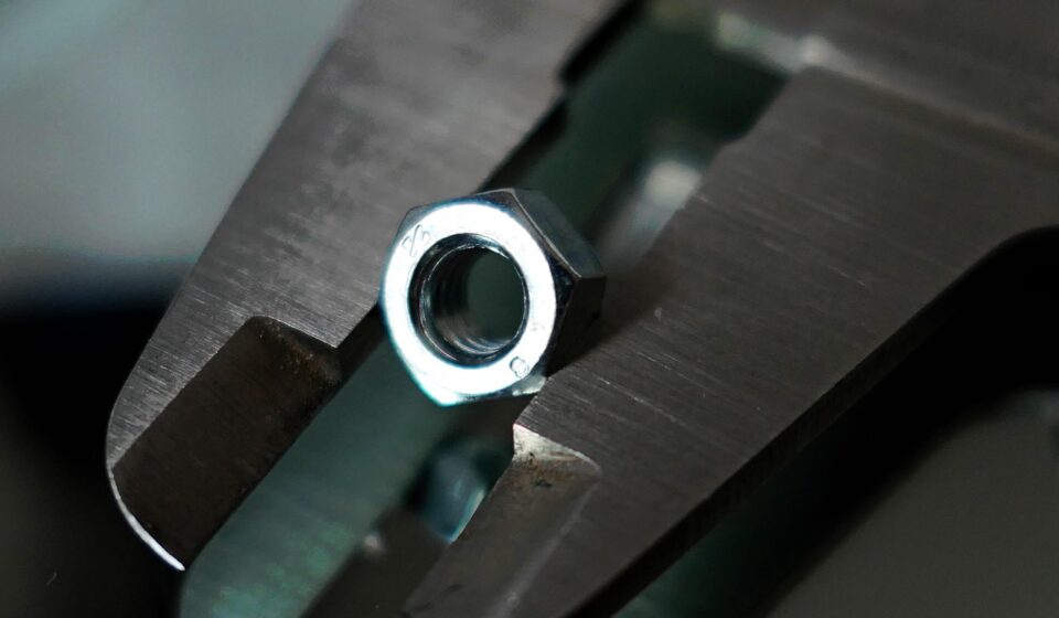
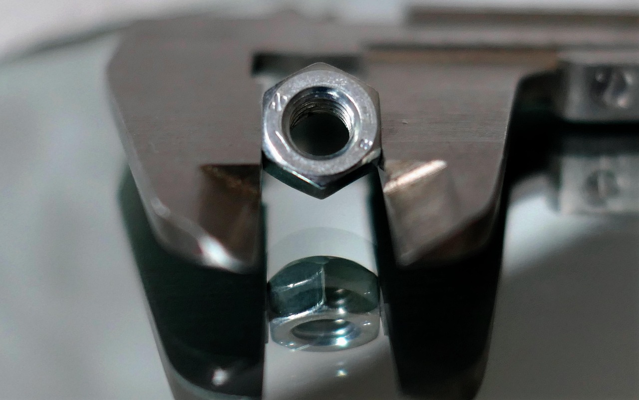
Common inspection tools include micrometers, bore gauges, plug gauges, ring gauges, thread gauges, surface roughness testers, optical comparators and coordinate measuring machines. The appropriate method depends on feature size, tolerance, geometry and production volume. For example, a precision ground gauge may be more practical for recurring shop-floor checks than a full CMM routine, while a CMM may be appropriate for first article inspection or complex datum relationships.
Quality-system context also matters. ISO 9001 addresses quality management system requirements across many industries. ISO 13485 is relevant for medical-device quality management systems, while aerospace, automotive and other regulated sectors may add customer-specific documentation, traceability and approval expectations. These frameworks do not replace the drawing; they define how requirements are controlled, recorded and reviewed.
What to include in an RFQ for precision turned components
A strong request for quotation should make the manufacturing problem visible. At minimum, include a 2D drawing, 3D model if available, material grade, heat treatment, finish, quantity, target delivery, critical dimensions, inspection requirements and packaging requirements. If the part has a functional interface, explain it briefly: rotating fit, press fit, sealing diameter, electrical contact, cosmetic surface, fluid passage or safety-critical assembly.
The drawing should separate critical-to-function dimensions from general dimensions. It should also define threads, undercuts, chamfers, radii, surface finish, burr expectations and datum structure. If special documentation is needed, such as material certification, first article inspection, process capability reporting or lot traceability, state it early. Adding these requirements after pricing can change cost and schedule.
For repeat orders, provide annual volume expectations and release patterns when possible. A prototype order of 20 pieces and a production order of 50,000 pieces may use different workholding, inspection strategy and even different machine types. Clear volume information helps the supplier quote a route that matches the real manufacturing need.
Common design choices that improve manufacturability
- Use standard bar sizes where the design allows it, because excessive stock removal increases cycle time and material waste.
- Avoid very deep, narrow grooves unless they are functionally necessary.
- Keep wall thickness realistic for the material and length-to-diameter ratio.
- Specify tight tolerances only on features that control fit, motion, sealing or alignment.
- Provide clear reliefs for threads and shoulders so tools can exit cleanly.
- Define allowable edge breaks and burr limits in functional areas.
- Review whether a milled feature can be moved, simplified or combined with another operation.
These choices do not weaken the design. They help align the design with a stable machining process, which is usually more valuable than achieving an unnecessarily complex feature at the quoting stage.
Frequently asked questions
What is the difference between CNC turned components and precision turned components?
CNC turned components are parts made on computer-controlled turning equipment. Precision turned components place more emphasis on controlled tolerances, repeatability, surface finish, inspection and fit with related assemblies. The difference is less about the machine name and more about the level of specification and verification required.
When should Swiss-type turning be considered?
Swiss-type turning is worth considering for small, slender or high-volume parts where bar support near the cutting tool helps control deflection. It can also be efficient for complex small parts with several operations in one cycle. It is not automatically needed for every small component, so geometry, volume and tolerance should guide the choice.
Do all turned parts need very tight tolerances?
No. Tight tolerances should be reserved for functional features. General features can often use broader tolerances without reducing performance. This approach lowers machining and inspection burden while keeping attention on the dimensions that actually control assembly and service behavior.
Why do quotes for the same turned part vary so much?
Different suppliers may assume different machines, setups, inspection levels, deburring effort, material yield and documentation requirements. A detailed drawing and RFQ reduce those assumptions. If quotes still vary widely, the difference often reveals uncertainty in tolerance interpretation, secondary operations or quality documentation.
What standards are commonly referenced on drawings?
Drawings may reference standards for fits, general tolerances, GD&T, threads, material, surface finish or quality systems. ISO 286, ISO 2768 and ASME Y14.5 are common examples in mechanical drawings, while ISO 9001 or ISO 13485 may be relevant to quality-system expectations. The drawing or contract should state the exact requirement rather than relying on informal assumptions.