Metal precision components and the factors that define manufacturing quality
What metal precision components mean in practice
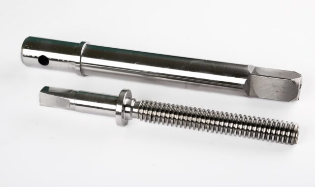
Metal precision components are metal parts whose geometry, material condition, surface quality, and verification records are controlled closely enough to support repeatable assembly and function. In manufacturing, precision does not mean making every dimension as tight as possible. It means applying the right tolerance to the features that matter, measuring those features with suitable equipment, and keeping the part stable through machining, finishing, assembly, and service. For readers following the broader topic, related updates are collected under precision components.
In engineering, purchasing, and production discussions, the practical question is usually the same: what separates a normal machined part from a true precision component? The answer is not one number on a drawing. It is the combination of clear design intent, capable processes, predictable material behavior, and disciplined inspection. A part with tight nominal tolerances can still fail if datum references are unclear, if heat treatment causes distortion, or if the selected inspection method cannot reliably prove conformity.
The specifications that decide whether a component is precise
Precision starts with the drawing or model. A manufacturing team cannot consistently produce a precise part unless the design defines which features are critical, how those features relate to one another, and what variation is acceptable. Standards such as ASME Y14.5-2018 provide a recognized language for dimensioning and tolerancing, including geometric dimensioning and tolerancing. ISO systems use geometrical product specification standards to define similar controls.
Dimensional tolerance and GD&T
Linear tolerances control sizes such as length, diameter, width, and hole depth. Geometric tolerances control relationships such as position, flatness, perpendicularity, runout, profile, and concentricity. For metal precision components, geometric tolerancing is often more useful than simply tightening every plus-minus dimension, because assemblies usually depend on how features relate to datum surfaces, shafts, bores, or mating faces.
A bracket, for example, may meet its overall length requirement but still fail assembly if two mounting holes are not positioned correctly relative to a datum face. A shaft may have the correct diameter but create vibration if runout is not controlled. A valve body may pass basic length checks but leak if the sealing surface has the wrong flatness or surface texture. In each case, precision is tied to function, not only to a smaller tolerance value.
General tolerances and current standard awareness
General tolerances are useful for non-critical dimensions, but they should not replace explicit controls on critical features. ISO 2768-1:1989 is widely recognized for general tolerances on linear and angular dimensions without individual tolerance indications. In ISO documentation, older references to ISO 2768-2 should be reviewed carefully because ISO lists ISO 22081:2021 as the current standard for general geometrical specifications and general size specifications, with the document confirmed in 2026. This is especially important when legacy drawings are reused for new production or transferred to another supplier.
Surface finish, edge condition, and material condition
Surface roughness, burr control, edge breaks, residual stress, coating thickness, and heat treatment condition can all affect precision. A mating bore may need a controlled finish to reduce wear. A sealing face may require both flatness and surface texture control. A part used near a sensor may need a low burr risk because small chips can interfere with electrical or fluid performance. In these situations, the details are not cosmetic. They are part of the functional specification.
Materials and processes are chosen together
Material selection and manufacturing route need to be considered together. The same tolerance may be straightforward in one alloy and difficult in another because metals differ in machinability, hardness, thermal expansion, work hardening, and distortion after heat treatment. A strong material is not automatically the best choice if it makes a thin feature unstable or requires a finishing process that adds cost without improving function.
| Material group | Why it is used | Precision manufacturing considerations |
|---|---|---|
| Aluminum alloys | Low weight, good machinability, corrosion resistance depending on alloy and finish | Thermal expansion can affect measurement; thin walls may distort during clamping or finishing |
| Stainless steels | Corrosion resistance, strength, hygiene, temperature performance | Some grades work harden; tool selection, coolant, and burr control need attention |
| Alloy steels | Strength, wear resistance, fatigue performance, heat treatability | Heat treatment can change dimensions; grinding or final machining may be needed after hardening |
| Brass and copper alloys | Conductivity, machinability, corrosion behavior, fluid and electrical uses | Burrs, surface marking, and material softness may influence handling and inspection |
| Titanium alloys | High strength-to-weight ratio and corrosion resistance | Low thermal conductivity and springback can increase tool wear, heat, and process sensitivity |
Process selection follows the same logic. CNC milling and turning are common for complex precision components, but grinding, honing, lapping, electrical discharge machining, broaching, and controlled deburring may be required for particular features. Additive manufacturing can produce near-net metal forms, but precision surfaces and critical fits often still require machining or finishing. Stamping, forging, and casting can also be part of a precision route when they are followed by controlled secondary machining and inspection.
Why tighter tolerance can increase cost and risk
A tighter tolerance is not automatically better. It often requires more stable machines, sharper tools, slower cuts, controlled temperature, additional fixtures, more inspection time, and sometimes special finishing. It can also increase scrap risk because a smaller process window leaves less room for normal variation. For that reason, one of the most valuable design decisions is to tighten only the features that truly affect fit, motion, sealing, load transfer, or safety.
Cost pressure usually appears in three areas. Setup cost rises when a component needs custom fixturing or multiple datum-controlled operations. Cycle time rises when finishing passes, tool changes, or in-process checks are added. Verification cost rises when measurement requires a coordinate measuring machine, optical system, surface roughness tester, gauge study, or documented first article inspection.
There is also a technical risk. Very tight tolerances on thin or flexible parts can be misleading because the component may measure differently depending on clamping force, temperature, or inspection orientation. Precision manufacturing therefore requires agreement between design, production, and quality teams on how the part will be held, measured, and accepted.
Inspection closes the gap between drawing and part
Inspection is not a final formality. It is the system that connects design intent to manufacturing reality. NIST publications on machining and dimensional metrology repeatedly emphasize the role of measurement, process correction, and integrated metrology in improving machining outcomes. In practical terms, precision components need a measurement plan that matches the feature, tolerance, risk, and production volume.
Common inspection tools include micrometers, calipers, height gauges, bore gauges, plug gauges, ring gauges, CMMs, optical comparators, vision systems, surface roughness testers, and hardness testers. Each method has limits. A handheld gauge may be fast but operator-dependent. A CMM can capture complex geometry, but it needs correct programming, fixturing, temperature control, and uncertainty awareness. Optical systems are useful for small or delicate features, although surface reflectivity can affect results. See also: buying guides.
Documentation is part of the same quality system. For many metal precision components, useful records may include material certificates, heat treatment records, coating or plating thickness data, first article inspection reports, calibration records, control plans, and nonconformance history. ISO 9001-type quality management systems do not define a specific product geometry, but they emphasize documented processes, customer requirements, conformity, and continual improvement. In sourcing, certification should be checked against the exact site, scope, and valid date rather than assumed from a logo.
A practical checklist for manufacturable metal precision components
Before releasing or sourcing a precision component, teams should review the drawing and manufacturing plan against the real function of the part. The following checklist can reduce ambiguity and avoid unnecessary cost:
- Define the functional features that control fit, sealing, motion, electrical contact, alignment, or load transfer.
- Use datums that match how the part is assembled or used, not only how it looks in a model.
- Apply geometric tolerances where feature relationships matter more than simple size.
- Avoid very tight tolerances on non-critical features unless there is a clear reason.
- Specify material grade, heat treatment condition, coating, and surface finish where they affect performance.
- Check whether burrs, sharp edges, cleanliness, or residual chips could create assembly or safety problems.
- Confirm that every critical tolerance can be measured with available equipment and acceptable uncertainty.
- Decide whether first article inspection, statistical process control, or 100 percent inspection is appropriate.
- Review older drawings for outdated standard references, especially where general geometrical tolerances are involved.
- Consider the full manufacturing sequence, including roughing, stress relief, heat treatment, finishing, coating, cleaning, and packaging.
This checklist is most useful early in the project. Once a supplier, machine route, or fixture has been selected, drawing changes can become expensive. An early design-for-manufacturing review can often preserve the required function while relaxing features that do not affect performance.
How to compare suppliers or manufacturing routes
When comparing potential routes for metal precision components, the lowest quoted unit price is not always the lowest total cost. A route that depends on repeated rework, unclear inspection, or unstable material behavior may create delays and quality disputes. A stronger comparison looks at process capability, measurement capability, communication quality, documentation, and experience with similar geometries.
Useful questions include: Can the process hold the required tolerance over the expected batch size? Which features are inspected in-process, and which are inspected after completion? What happens if plating or heat treatment changes a critical dimension? Are gauges or CMM programs validated before production? Is the same datum scheme used in machining and inspection? These questions show whether precision is being managed as a system or treated as a final inspection problem.
For small batches, flexibility and engineering feedback may matter more than high automation. For larger volumes, repeatability, fixture robustness, tool-life monitoring, and statistical control become more important. For safety-critical or regulated applications, documentation and traceability may be as important as machining capability.
Frequently asked questions
What tolerance qualifies a part as a metal precision component?
There is no universal tolerance value that makes a part precise. A precision component is one whose tolerances, geometry, surface condition, and material requirements are controlled tightly enough for its intended function. A large machine base, a miniature medical part, and a hydraulic valve spool may all be precision components, but their critical features and measurement methods will differ.
Are all metal precision components made by CNC machining?
No. CNC machining is common, but precision components can also involve grinding, honing, EDM, lapping, stamping with secondary machining, casting with finish machining, forging with final grinding, or additive manufacturing followed by machining. The correct route depends on geometry, material, volume, tolerance, surface finish, and cost target.
Why do drawings use GD&T instead of only plus-minus tolerances?
GD&T controls how features relate to datums and to each other. This matters when assembly depends on position, flatness, runout, perpendicularity, or profile. Plus-minus tolerances are still useful for simple sizes, but they may not fully describe functional relationships in precision assemblies.
How does surface finish affect precision components?
Surface finish can influence friction, sealing, fatigue behavior, coating adhesion, cleanliness, and wear. A component can meet dimensional tolerance but still perform poorly if the surface texture is unsuitable for the application. Surface finish should be specified where it has a functional role, not merely as a cosmetic requirement.
What should buyers request besides the finished part?
Depending on risk, buyers may request material certificates, heat treatment records, coating data, first article inspection reports, dimensional reports, surface roughness results, calibration evidence, and packaging requirements. The required documentation should be agreed before production to avoid disputes after parts are completed.